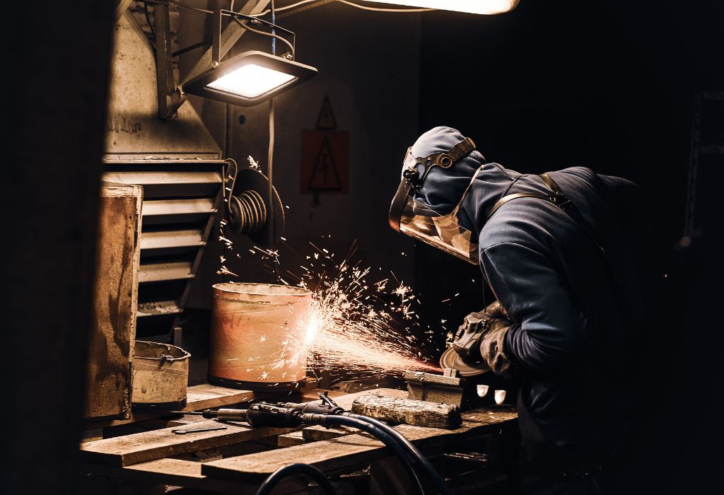
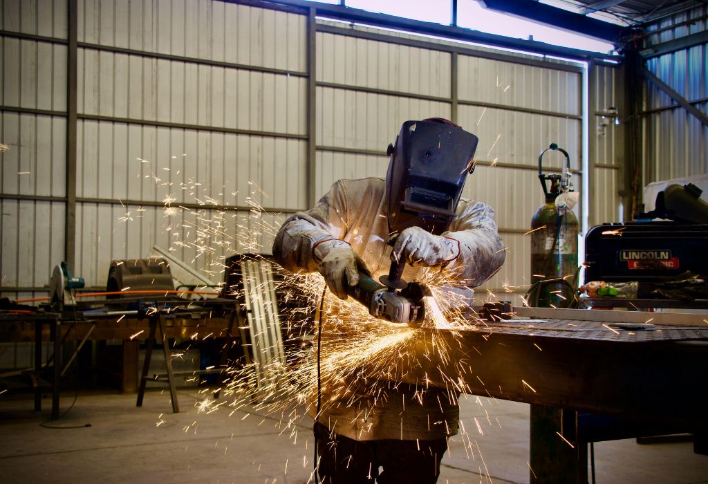
Welding parameters are the building blocks of every quality weld. They control heat, penetration, bead shape, and overall weld strength. Whether you are using MIG, TIG, Stick, or Flux-Cored welding, understanding these parameters is essential for producing defect-free welds.
For many beginners, terms like amperage, voltage, travel speed, and gas flow rate feel overwhelming. Yet these settings directly affect weld strength, appearance, and cost-efficiency. Incorrect parameters can lead to defects like porosity, undercut, or excessive spatter—problems that cost time and money to fix.
Industry research shows that over 50% of welding defects come from improper parameter settings (Source: AWS). On the other hand, skilled welders who master parameter control often deliver 20–30% higher productivity with fewer quality issues (Source: BLS).
This guide provides a complete beginner-friendly approach to welding parameters. You’ll learn:
- Key parameters like current, voltage, travel speed, and gas flow.
- Recommended settings for MIG, TIG, and Stick welding processes.
- Common welding defects caused by wrong parameters and how to fix them.
- Real-world applications across construction, automotive, aerospace, and energy industries.
By the end, you’ll understand how to set, adjust, and optimize welding parameters for stronger, cleaner, and more consistent welds in any environment.
What Are Welding Parameters?
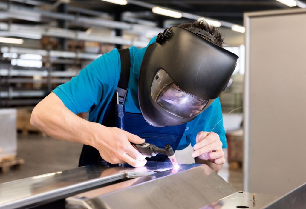
Welding parameters are the specific settings and conditions that control how heat, current, speed, and gas flow are applied during the welding process. These settings directly influence the strength, quality, and appearance of the finished weld.
In simple terms, welding parameters decide:
- How deep the weld penetrates the base metal.
- How wide or narrow the weld bead becomes.
- Whether the weld will be smooth, strong, and defect-free.
Every welding process—MIG, TIG, Stick, or Flux-Cored—uses parameters like amperage (current), voltage (arc length), travel speed, and shielding gas flow rate.
For example:
- In MIG welding, the wire feed speed and voltage work together to control bead shape and penetration.
- In TIG welding, parameters like amperage and gas flow rate ensure precision and cleanliness.
Learning to adjust these parameters properly helps beginners produce consistent, high-quality welds while avoiding defects like porosity, lack of fusion, or excessive spatter.
Why are welding parameters important?
They ensure proper heat control, penetration, and weld quality across different materials and thicknesses.
Do parameters vary by welding process?
Yes, MIG, TIG, Stick, and Flux-Cored welding require different parameter ranges for optimal results.
Can wrong parameters cause welding defects?
Absolutely. Incorrect settings often lead to weak welds, cracks, or excessive heat distortion.
Key Welding Parameters Explained
Welding quality depends on controlling a few critical parameters. Each parameter affects the strength, appearance, and performance of the weld.
Welding Current (Amperage)
- Definition: Amperage controls the amount of heat in the weld. Higher current = deeper penetration, while low current = shallow welds.
- Too High: Can cause burn-through, excessive spatter, or distortion.
- Too Low: Leads to weak welds, poor fusion, and lack of penetration.
- Example: In Stick welding, using E6011 electrodes at 100–130 amps gives better penetration on mild steel.
What is the ideal current for beginners?
Follow the electrode or wire manufacturer’s chart for recommended amperage based on material thickness.
Welding Voltage (Arc Length)
- Definition: Voltage controls the arc length and bead width. Higher voltage creates wider, flatter beads, while low voltage makes narrower, taller beads.
- Too High: Produces excessive spatter and weak arcs.
- Too Low: Causes uneven beads and poor penetration.
- Example: MIG welding mild steel usually needs 17–22 volts for good results.
Why is arc length important?
Arc length affects stability and heat distribution, impacting weld quality and appearance.
Travel Speed
- Definition: The speed at which the welding torch or electrode moves along the joint.
- Too Fast: Leads to narrow, underfilled welds with lack of fusion.
- Too Slow: Causes overheating, wide beads, and excess reinforcement.
- Example: For MIG welding 1/4″ steel, a moderate travel speed ensures good fusion without distortion.
How to maintain correct speed?
Use consistent hand motion and watch the molten pool size to guide travel speed.
Wire Feed Speed (for MIG Welding)
- Definition: Controls the amount of filler metal supplied to the weld.
- Too Fast: Can cause excessive buildup and spatter.
- Too Slow: Leads to gaps, uneven beads, and unstable arcs.
- Example: Typical settings for 0.030″ wire on mild steel: 250–350 inches per minute (IPM).
How is wire feed speed related to amperage?
Higher wire speed increases amperage, affecting penetration and bead size.
Shielding Gas Flow Rate
- Definition: Controls the amount of shielding gas protecting the weld pool from atmospheric contamination.
- Too High: Causes turbulence, pulling in air and creating porosity.
- Too Low: Leads to oxidation and weak welds.
- Example: MIG welding mild steel with 75/25 Argon-CO₂ mix typically uses 20–25 CFH (cubic feet per hour).
Why is shielding gas important?
It prevents oxygen, nitrogen, and hydrogen from entering the weld pool, avoiding porosity and cracking.
Electrode Angle and Position
- Definition: The angle between the electrode and workpiece affects bead shape and penetration.
- Common Angles: 10–15° push angle for MIG, 15–20° drag angle for Stick welding.
- Effect: Wrong angles cause undercutting, overlap, or inconsistent bead shapes.
What’s the best angle for beginners?
For flat MIG welding, maintain a 10–15° push angle for smooth, consistent beads.
Heat Input Control
- Definition: Total energy delivered to the weld per unit length.
- Formula: Heat Input = (Volts × Amps × 60) ÷ Travel Speed.
- Importance: Excess heat causes distortion, while low heat leads to lack of fusion.
How to control heat input?
Adjust voltage, amperage, and travel speed together for balanced heat distribution.
Factors Affecting Welding Parameters
The correct choice of welding parameters depends on several factors. Adjusting settings based on material, position, and joint design helps produce strong, defect-free welds in real-world projects.
Material Thickness
- Effect: Thicker materials require higher amperage and voltage for deeper penetration.
- Example: Welding 1/2″ structural steel may need 220+ amps, while thin sheet metal (18–20 gauge) requires much lower settings around 50–90 amps.
- Tip: Always follow recommended parameter charts for the base metal thickness.
Why is thickness so important?
Too little heat on thick metals causes lack of fusion, while too much heat on thin metals leads to burn-through.
Welding Position
- Effect: Positions like vertical and overhead need lower heat input compared to flat positions to prevent metal from dripping or sagging.
- Example: A 3G (vertical) weld typically uses lower amperage than a 1G (flat) weld for the same material thickness.
- Tip: Use stringer beads with lower heat settings for vertical or overhead welding.
Do all positions require different settings?
Yes, especially for overhead and vertical welds where gravity affects the molten pool.
Joint Design
- Effect: Butt joints, lap joints, and T-joints need different penetration levels and travel speeds.
- Example: A single-V groove joint requires more heat input than a fillet weld on a lap joint.
- Tip: Complex joints may need multiple passes with parameter adjustments between layers.
Why adjust parameters for each joint type?
To achieve full penetration without overheating or excessive reinforcement.
Welding Process
- Effect: MIG, TIG, Stick, and Flux-Cored welding each have unique parameter ranges.
- Example: MIG welding uses wire feed speed charts, while Stick welding relies on electrode diameter and amperage charts.
Can one setting work for all processes?
No, each process needs specific settings for optimal weld quality.
Material Type
- Effect: Stainless steel, aluminum, and carbon steel require different voltage, amperage, and shielding gas settings.
- Example: Aluminum needs higher heat input and pure argon gas for clean welds, while steel may use a CO₂-argon mix.
Why is material type critical for parameter choice?
Different metals conduct heat differently and have unique chemical properties affecting weld quality.
Recommended Parameter Settings for Common Processes
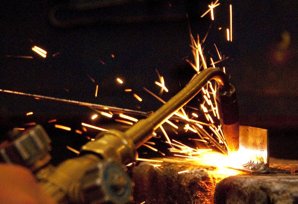
Choosing the correct parameter settings depends on welding process, material type, and thickness. Below are typical settings for MIG, TIG, and Stick welding to help beginners get started.
MIG Welding (GMAW) Settings Table
| Material Thickness | Wire Diameter | Amperage (A) | Voltage (V) | Wire Feed Speed (IPM) | Gas Flow (CFH) |
| 1/16″ (1.6 mm) | 0.023″ | 40–90 | 16–18 | 200–300 | 20–25 |
| 1/8″ (3.2 mm) | 0.030″ | 90–140 | 17–20 | 250–350 | 20–25 |
| 1/4″ (6.4 mm) | 0.035″ | 140–200 | 20–22 | 300–400 | 25–30 |
| 3/8″ (9.5 mm) | 0.045″ | 200–275 | 22–26 | 350–450 | 25–30 |
Tip: Use 75% Argon / 25% CO₂ for mild steel to reduce spatter and improve bead quality.
TIG Welding (GTAW) Settings Table
| Material Type | Thickness | Amperage (A) | Tungsten Diameter | Gas Flow (CFH) | Polarity |
| Stainless Steel | 1/16″ (1.6 mm) | 50–100 | 1/16″ (1.6 mm) | 15–20 | DCEN (DC Electrode -) |
| Aluminum | 1/8″ (3.2 mm) | 100–160 | 3/32″ (2.4 mm) | 15–20 | AC |
| Carbon Steel | 1/4″ (6.4 mm) | 150–250 | 1/8″ (3.2 mm) | 20–25 | DCEN |
Tip: Use pure argon gas for aluminum and stainless steel to avoid oxidation and porosity.
Stick Welding (SMAW) Settings Table
| Electrode Type | Diameter | Amperage Range (A) | Polarity | Common Applications |
| E6010 / E6011 | 1/8″ (3.2 mm) | 75–125 | DCEP (DC Electrode +) | Pipelines, structural welding |
| E6013 | 1/8″ (3.2 mm) | 80–130 | AC or DCEP | Sheet metal, light structures |
| E7018 | 1/8″ (3.2 mm) | 90–150 | DCEP | Bridges, pressure vessels |
Tip: Always follow the electrode manufacturer’s recommendation for best results.
Common Welding Defects Caused by Wrong Parameters
Incorrect parameter settings often lead to defects that weaken weld strength, reduce appearance quality, and increase repair costs. Understanding these issues helps beginners adjust parameters before serious problems occur.
Porosity
- Cause: Too low shielding gas flow, contaminated base metal, or excessive arc length.
- Effect: Tiny gas pockets inside the weld, leading to weak, porous joints.
- Correction: Clean base metal, maintain correct gas flow (20–25 CFH), and reduce arc length.
Undercut
- Cause: Excessive travel speed or too high amperage.
- Effect: Grooves along the edges of the weld bead, reducing cross-sectional strength.
- Correction: Slow down travel speed, reduce current, and maintain correct torch angle.
Lack of Fusion
- Cause: Too low amperage, improper joint preparation, or fast travel speed.
- Effect: Weld metal fails to fuse properly with the base metal, causing weak joints.
- Correction: Increase heat input, improve edge preparation, and maintain steady travel speed.
Overlap
- Cause: Slow travel speed or excessive filler deposition.
- Effect: Weld metal extends beyond the weld toe without fusing, creating weak areas.
- Correction: Increase travel speed slightly and control filler material flow.
Excessive Spatter
- Cause: Too high voltage or incorrect polarity settings.
- Effect: Small metal particles around the weld bead, reducing appearance quality.
- Correction: Lower voltage, use correct polarity, and adjust wire feed speed for MIG welding.
Cracking
- Cause: Excessive heat input, wrong filler metal, or rapid cooling rates.
- Effect: Cracks form in or near the weld, leading to structural failures.
- Correction: Preheat thicker materials, control heat input, and use proper filler metal.
Which defect is most common for beginners?
Porosity and undercut often occur when shielding gas or travel speed settings are incorrect.
Can parameter charts prevent welding defects?
Yes, following recommended settings minimizes errors and ensures consistent quality.
Techniques for Optimizing Welding Parameters
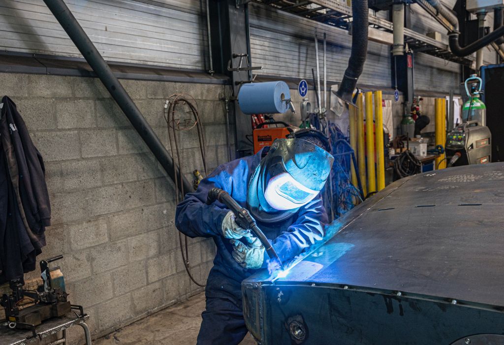
Optimizing welding parameters is essential for consistent quality, higher productivity, and fewer defects. Beginners can follow simple steps to set parameters correctly and use advanced tools for better control.
1. Follow Welding Procedure Specifications (WPS)
- What it is: A WPS is a document outlining recommended settings for current, voltage, travel speed, and filler materials for a specific job.
- Why it helps: Ensures welds meet industry standards like AWS D1.1 or ASME Section IX.
- Example: A pipeline project WPS might specify 120 amps, 20 volts, and a 10° torch angle for vertical welds.
Tip: Always review the WPS before starting any certified welding project.
2. Use Parameter Charts from Manufacturers
- Purpose: Electrode and filler wire manufacturers provide charts for amperage, voltage, and wire feed speed based on material thickness and welding position.
- Example: E7018 Stick electrodes often require 90–150 amps for 1/8″ rods.
Tip: Beginners should keep printed parameter charts in the workshop for quick reference.
3. Perform Test Welds Before Production
- Purpose: Small test welds help verify settings for penetration, bead shape, and appearance before large-scale welding.
- Example: Use scrap metal pieces to fine-tune amperage and travel speed settings.
Tip: Check weld cross-sections for proper penetration and fusion.
4. Monitor Heat Input Closely
- Why it matters: Excess heat causes distortion, while low heat leads to lack of fusion.
- Solution: Use the heat input formula: (Volts × Amps × 60) ÷ Travel Speed = Heat Input (kJ/in).
Tip: Maintain consistent travel speed to control total heat input.
5. Use Digital and Automated Welding Systems
- Modern tools: CNC welding machines, digital parameter loggers, and robotic welding arms store and control parameter settings automatically.
- Benefit: Improves accuracy, reduces operator error, and ensures repeatability in mass production.
Tip: Automated systems are widely used in automotive, aerospace, and energy sectors for precision welding.
Do professionals adjust parameters manually or automatically?
Both methods are common, but automation is preferred for high-volume and critical welds.
Are WPS documents mandatory for every project?
They are required for most industrial and certified welding projects to meet safety codes.
Practical Applications of Welding Parameters in Industry
Welding parameters directly influence strength, quality, and safety across multiple industries. Adjusting settings for each application ensures consistent performance and cost efficiency.
Construction Industry
- Use Case: Bridges, skyscrapers, offshore platforms, and pipelines.
- Parameter Focus: High amperage and proper heat input are essential for thick structural materials.
- Example: Vertical welds on building frames often use lower travel speeds to prevent undercutting and ensure full penetration.
Which parameters matter most in construction?
Amperage, voltage, and travel speed are critical for structural integrity and meeting building codes.
Automotive Manufacturing
- Use Case: Car frames, exhaust systems, and robotic assembly lines.
- Parameter Focus: Wire feed speed and voltage must be optimized for robotic MIG welding.
- Example: Thin automotive panels require low amperage and high travel speed to prevent burn-through.
Why is parameter control important in automotive welding?
It ensures repeatable quality and prevents distortion on lightweight sheet metal parts.
Aerospace Industry
- Use Case: Aircraft frames, engine components, and fuel tanks.
- Parameter Focus: TIG welding parameters like gas flow rate and amperage must be precise for lightweight alloys.
- Example: Aerospace welds often require low heat input to avoid warping thin materials like aluminum or titanium.
Do aerospace welders use standard parameter charts?
Yes, but parameters are often tighter due to strict safety and quality requirements.
Energy Sector
- Use Case: Oil & gas pipelines, wind turbine towers, and nuclear reactors.
- Parameter Focus: High amperage for thick pipes, controlled heat input to prevent cracking in pressure vessels.
- Example: Pipeline welding uses cellulosic Stick electrodes with specific amperage ranges for deep penetration.
Why is heat input control critical in the energy sector?
It prevents defects like cracking or hydrogen embrittlement in high-pressure environments.
Visual Guides for Welding Parameters
For beginners, welding parameters can feel overwhelming. Charts, diagrams, and infographics simplify complex data, making it easier to understand relationships between settings like amperage, voltage, travel speed, and gas flow rate.
Recommended Visual Guides
1. Welding Parameter Charts
- Show ideal settings for different processes (MIG, TIG, Stick) based on material thickness.
- Include amperage, voltage, wire feed speed, and gas flow recommendations.
2. Heat Input Graphs
- Illustrate how changes in voltage, amperage, and travel speed affect total heat input.
- Help welders prevent distortion and cracking in sensitive materials.
3. Defect Troubleshooting Flowcharts
- Visual guides listing common welding defects with causes and parameter corrections.
- For example: Porosity → Check gas flow → Clean base metal → Reduce arc length.
4. Shielding Gas Selection Diagrams
- Color-coded charts showing recommended gas types and flow rates for MIG, TIG, and Flux-Cored welding.
5. Electrode/Wire Selection Tables
- Visual tables linking electrode diameter, amperage range, and polarity for Stick and MIG welding processes.
Why Visual Aids Improve Learning
Studies show learners retain up to 65% more information when text is combined with visuals (Source).
- Welding schools use wall posters and digital slides for parameter training.
- Interactive 3D welding simulators now include parameter adjustment practice.
Can beginners download free parameter charts?
Yes, many welding equipment manufacturers like Lincoln Electric and Miller provide free downloadable charts on their websites.
FAQs About Welding Parameters
1. What are the most important welding parameters?
Current (amperage), voltage, travel speed, wire feed speed, shielding gas flow, and electrode angle are the key parameters for most processes.
2. How do I choose the right welding parameters?
Follow WPS (Welding Procedure Specifications) or parameter charts from welding equipment manufacturers for material thickness and process type.
3. Which parameter affects weld penetration the most?
Amperage primarily controls penetration, while voltage affects bead width and appearance.
4. How does travel speed affect weld quality?
Too fast causes lack of fusion, while too slow overheats the metal and increases distortion.
5. Why is shielding gas flow rate important?
It protects the molten weld pool from contamination by oxygen, nitrogen, and moisture.
6. Can wrong parameters cause welding defects?
Yes, improper settings lead to porosity, undercut, overlap, lack of fusion, and cracking.
7. Are parameter settings the same for all welding processes?
No, MIG, TIG, Stick, and Flux-Cored welding each have unique parameter ranges.
8. How do I control heat input in welding?
Adjust voltage, amperage, and travel speed together to maintain proper heat input levels.
9. Do overhead and vertical welds need different parameters?
Yes, lower heat settings and slower travel speeds are often used to control the molten pool.
10. Can automation help with parameter control?
Modern welding machines and robotic systems store parameter presets for consistent, repeatable welds.
11. Are there standard tables for welding parameters?
Yes, AWS, ASME, and equipment manufacturers provide parameter reference tables for common materials and processes.
12. How do I fix excessive spatter in MIG welding?
Reduce voltage slightly, optimize wire feed speed, and maintain correct torch angle and travel speed.
Conclusion
Mastering welding parameters is essential for producing strong, clean, and defect-free welds in any industry. From construction and automotive manufacturing to aerospace and energy projects, correct parameter control ensures structural integrity, cost efficiency, and safety compliance.
In this guide, we explored:
- The key welding parameters like amperage, voltage, travel speed, wire feed speed, and gas flow rate.
- How material thickness, joint design, and welding positions influence parameter settings.
- Common welding defects caused by incorrect settings and how to fix them.
- Recommended parameter tables for MIG, TIG, and Stick welding processes.
- Real-world applications and modern tools for parameter optimization.
For beginners, the best approach is to start with manufacturer charts or WPS guidelines, perform test welds on scrap metal, and gradually learn how each parameter affects weld quality.
As industries adopt digital welding machines, robotic systems, and automation, understanding parameters will remain a critical skill for both manual and automated welding operations.
By mastering welding parameters, you’ll improve weld quality, reduce defects, and advance your career as a skilled, certified welder ready for industrial projects worldwide.

I’m Darrell Julian, the founder, lead writer, and hands-on welding enthusiast behind ArcWeldingPro.com. With more than 15 years of real-world welding experience, I created this platform to share what I’ve learned in the field, in the shop, and in the heat of the arc.

