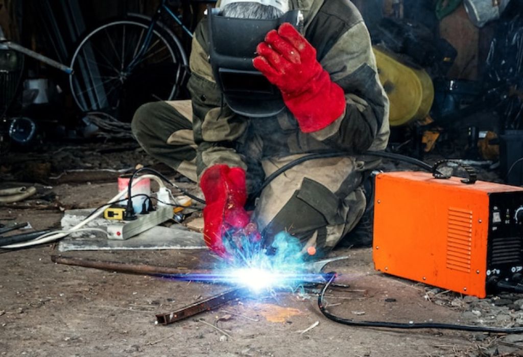
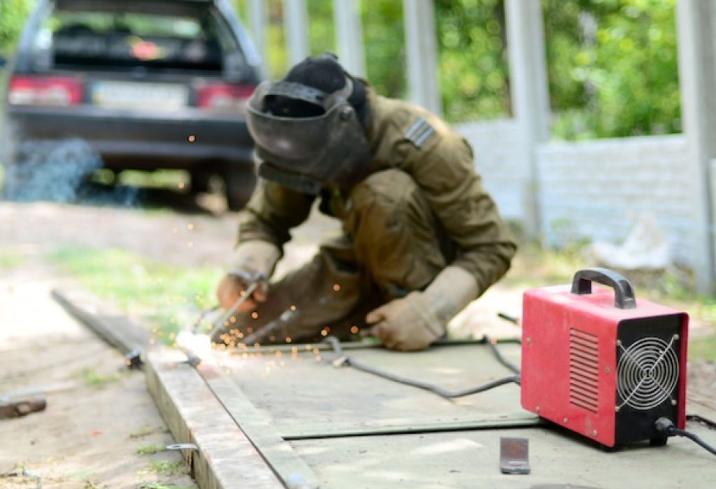
A welder prepares to start a new project but notices the machine’s arc feels weaker than usual. The beads look uneven, and the sound of the weld just isn’t right. Something is clearly off, yet the voltage reading on the machine’s display seems normal.
Voltage accuracy plays a critical role in welding performance, but it is often misunderstood or overlooked. A simple misreading can lead to poor penetration, excessive spatter, or even equipment damage.
According to industry findings, more than 30% of welding defects are caused by incorrect electrical parameters (source).
Most welders assume the number on the panel reflects actual voltage at the arc, but that’s rarely true. Voltage loss along cables, connections, and internal resistance can create deceptive readings.
As a result, welders may spend hours troubleshooting technique issues when the real problem lies in the electrical setup.
Understanding how to check voltage on welding machine correctly ensures both quality and safety. It helps maintain consistent heat input, stable arc behavior, and cleaner weld finishes. Studies also show that maintaining proper voltage can extend electrode life by up to 25% (source).
Understanding Voltage in Welding

Every welding process depends on one simple factor: the control of electrical energy. Voltage is the driving force that pushes current through the circuit, determining how hot the arc burns and how the weld pool behaves.
Without the right voltage, even the most skilled welder will struggle to achieve strong, consistent results.
Voltage represents the electrical pressure between two points — in this case, between the electrode and the workpiece.
In welding, it directly influences arc length, bead shape, and penetration depth. Higher voltage widens the weld bead and smoothens the arc, while lower voltage narrows the bead and increases the chance of spatter or porosity.
To understand how to check voltage on welding machine, it’s important to differentiate between open circuit voltage (OCV) and arc voltage.
OCV is the voltage measured when the circuit is open — before striking the arc. Arc voltage, on the other hand, is the voltage under load when welding actually takes place.
The difference between these two readings reveals how efficiently the machine delivers power through cables, connectors, and electrodes.
Different welding machines also behave differently. Constant voltage (CV) machines, often used for MIG or flux-cored welding, automatically adjust current to maintain voltage.
Constant current (CC) machines, typically used for TIG or stick welding, hold current steady while voltage fluctuates with arc length. Knowing this helps when comparing readings and troubleshooting inconsistencies.
What is open circuit voltage (OCV)?
It is the voltage measured at the output terminals when no arc is struck or no current flows.
What is arc voltage?
It is the voltage across the electrode and workpiece while welding is active and current is flowing.
Why does arc voltage differ from the display reading?
Because voltage drops occur due to cable resistance, connections, and internal losses within the machine.
How does voltage affect the weld bead?
Higher voltage flattens and widens the bead, while lower voltage makes it narrow and convex.
Why do CV and CC machines behave differently?
CV machines stabilize voltage automatically, whereas CC machines let voltage vary based on arc length and operator control.
Common Challenges and Mistakes When Checking Voltage
Even experienced welders sometimes misinterpret voltage readings because small technical details can cause big discrepancies.
A machine may appear to run at the correct setting, yet the actual voltage at the arc may be far lower due to hidden losses. Understanding these common mistakes is essential before applying any measurement method.
Many errors occur because voltage is measured at the wrong points or under the wrong conditions. Measuring without load, for example, only shows the open circuit voltage (OCV), which is always higher than the arc voltage.
The difference between these two can easily reach several volts, leading to false assumptions about machine performance.
Cable length, connector condition, and lead gauge also play major roles. Long or undersized cables increase resistance and voltage drop, resulting in weaker arcs even when the panel shows the correct setting. Poorly tightened terminals or corroded connectors can worsen the effect, making voltage readings unstable.
Another common challenge involves interference from electromagnetic fields created by the arc itself.
This interference can cause fluctuations on digital meters, especially if the meter lacks proper shielding. Choosing a high-quality, insulated meter with differential measurement capability helps minimize this problem.
Why do measured voltages differ from panel readings?
Because voltage drops across cables and connectors, causing the actual arc voltage to be lower than the display value.
Can cable length affect voltage accuracy?
Yes. The longer the cable, the greater the resistance and voltage loss.
Why should voltage be measured under load instead of open circuit?
Only under load does the reading reflect real welding conditions and true arc voltage.
What causes fluctuating readings on a meter?
Arc instability, electromagnetic interference, or poor grounding connections.
Can using the wrong probe type create errors?
Yes. Improper or non-insulated probes can cause inaccurate readings or even safety hazards.
Tools and Equipment Needed to Check Voltage
Checking welding voltage requires accuracy, consistency, and proper instruments. Using the wrong tools or measuring incorrectly can result in misleading data that affects weld quality and equipment performance. Reliable tools not only ensure precision but also keep the welder safe during measurement.
The most essential tool is a digital multimeter or welding voltmeter capable of handling high-current environments. The meter must have insulated probes rated for welding applications.
Many professionals prefer a differential probe or floating voltmeter because they isolate measurement points, reducing the risk of shock and interference.
A clamp meter can also be used to monitor current flow, helping welders compare voltage and current simultaneously.
For accurate readings, probe connections should be made as close to the torch tip and work clamp as possible. Measuring only from the machine’s terminals can miss real voltage drops occurring along the cable.
Proper personal protective equipment (PPE) is equally important. Insulated gloves, eye protection, and fire-resistant clothing prevent accidents during active testing.
It’s also recommended to keep cables clean, connections tight, and meters calibrated regularly for consistent results.
Which types of meter are suitable for voltage testing?
Digital multimeters, clamp meters, or dedicated welding voltmeters designed for industrial use.
Do you need isolation when testing?
Yes. Using an isolated or differential meter prevents electrical shock and interference.
Where should probes be connected?
Between the torch or electrode holder and the work clamp to measure true arc voltage.
Is current measurement necessary too?
Yes. Measuring both voltage and current helps verify the power output and detect voltage drop.
How to ensure meter accuracy?
Regular calibration, clean probe tips, and proper range settings maintain reliable readings.
Step-by-Step: How to Check Voltage on Welding Machine

Voltage measurement in welding is more than attaching a meter and reading numbers. It requires precision, timing, and awareness of both electrical and safety factors. Following a systematic process ensures accuracy and prevents potential hazards while testing live circuits.
Before beginning, make sure all cables are in good condition and connections are tight. A simple loose terminal can alter readings by several volts. Always use insulated tools and wear protective gear to avoid electrical shocks or accidental burns during measurement.
Step 1: Prepare the Machine and Setup
Turn off the welding machine and inspect all components. Ensure the power source, cables, and connectors are clean and dry. Confirm that the machine is properly grounded before proceeding.
Should the machine be warmed up first?
Yes. Allow it to run for a few minutes to stabilize internal voltage levels.
Is it safe to test with power off?
Initial setup can be done with power off, but accurate voltage testing requires live measurement under load.
Step 2: Connect Meter Leads Correctly
Attach the meter’s positive lead to the electrode holder or torch side output and the negative lead to the work clamp. Place probes as close to the arc as possible for accurate readings.
Can leads be reversed?
Yes, but it will invert the polarity of the reading. Maintaining correct polarity helps avoid confusion.
Where is the best probe placement?
At the torch tip and work clamp for true arc voltage, not just at the machine’s output terminals.
Step 3: Strike an Arc and Apply Load
Start welding at the desired setting to measure voltage during operation. Maintain a steady arc for several seconds to stabilize the reading.
Should the arc be continuous?
Yes. Short interruptions can cause voltage spikes or drops that distort the average reading.
How long should readings be recorded?
Take multiple samples over a few seconds and average them for accuracy.
Step 4: Record and Interpret Readings
Compare the measured value with the machine’s display or the expected specification. If there is a significant difference, it often indicates voltage loss through cables or connectors.
What is an acceptable difference?
Typically ±1–2 volts is within tolerance for most welding machines.
What causes voltage to drop?
Worn connectors, corroded cables, or excessive resistance in the leads.
Step 5: Test at Different Settings
Repeat the procedure across various voltage levels and welding modes to identify irregularities. Document all readings for future calibration or maintenance checks.
Should both high and low ranges be tested?
Yes. This helps detect inconsistent power output or drifting calibration.
Do temperature or duty cycle affect results?
Yes. Overheating or high-duty operation can cause minor voltage fluctuations due to resistance changes.
By following this structured method, welders can confidently verify that the machine delivers the correct output at the arc, ensuring consistent weld quality and reducing rework time.
Conclusion
Learning how to check voltage on welding machine the right way is essential for both performance and safety.
Voltage isn’t just a number on your display — it defines the strength, penetration, and smoothness of every weld.
When voltage is too high, the weld may burn through or spatter excessively.
When it’s too low, the bead becomes weak, uneven, and poorly fused to the base metal.
By checking voltage correctly with a digital multimeter or the welder’s built-in meter, you ensure accurate readings that match the metal type and wire size.
This precision allows you to fine-tune your setup for consistent arc stability and cleaner welds.
According to the American Welding Society, proper voltage calibration can improve weld quality by up to 25% and reduce costly rework in professional and home workshops alike.
It also extends equipment lifespan by preventing overheating and power fluctuations.
In short, understanding how to check voltage on welding machine the right way keeps your welds strong, your tools protected, and your results professional.
Taking a few moments to verify voltage before every job is one of the simplest habits that separates great welders from average ones.

I’m Darrell Julian, the founder, lead writer, and hands-on welding enthusiast behind ArcWeldingPro.com. With more than 15 years of real-world welding experience, I created this platform to share what I’ve learned in the field, in the shop, and in the heat of the arc.


