A new TIG welder arrives in the workshop, gleaming with promise, yet it refuses to start.
The cables look right, the gas bottle is full, and the pedal is plugged in, but the arc won’t ignite.
For many welders, the problem isn’t the machine itself—it’s the way it’s connected.
Incorrect setup is one of the most common issues that stop TIG welders from performing properly.
A reversed polarity, loose ground, or misaligned gas hose can lead to weak arcs and contaminated welds.
According to The Fabricator, improper electrical and gas connections cause up to 25% of welding performance issues in new setups.
TIG welding is a process that thrives on precision.
Even a minor mistake in connection can disrupt shielding gas flow, overheat cables, or damage expensive components.
That’s why learning how to connect TIG welding machine the right way is essential before striking the first arc.
A well-connected TIG setup ensures consistent current flow, stable arc starts, and clean weld beads free from porosity.
It also prevents safety hazards like electric shock, gas leaks, and overheating.
As noted by Lincoln Electric, regular connection checks can extend machine life by up to 40%.
Basics of TIG Machine Connections and Terminology
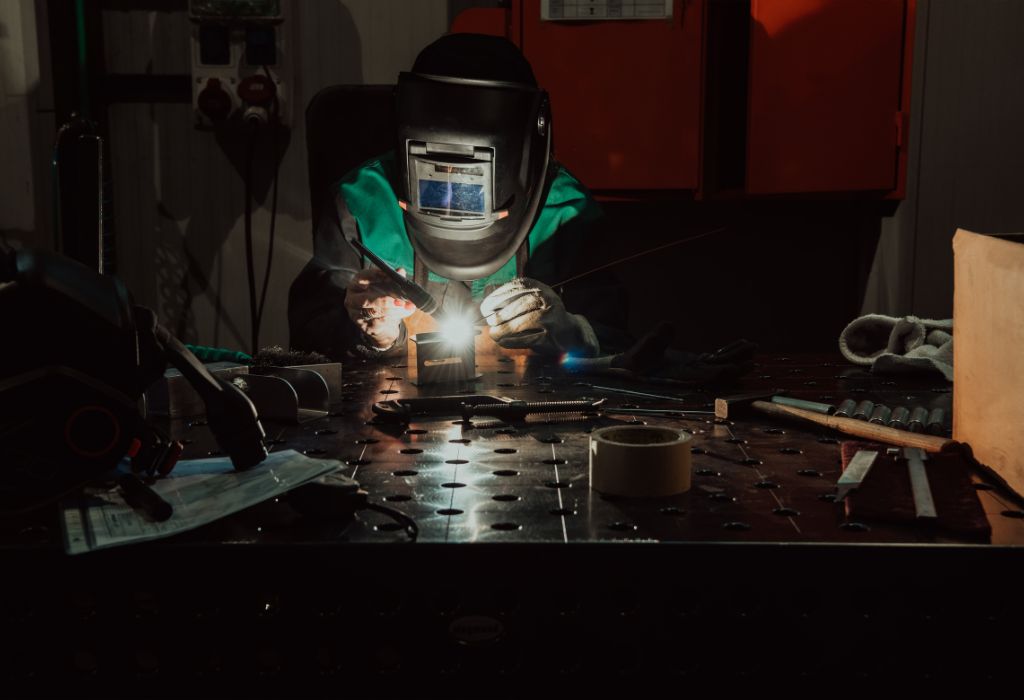
Before connecting a TIG welding machine, it’s essential to understand how each component works together.
A TIG system consists of several key parts—each performing a specific function to create a stable, clean, and controlled welding process.
The TIG torch is the centerpiece of the setup.
It carries the electrical current to the tungsten electrode, which generates the arc that melts the base metal.
Inside the torch, a collet and collet body hold the tungsten firmly, while a back cap seals it and ensures proper gas flow.
The ground or work clamp is just as vital.
It completes the electrical circuit between the welding machine and the workpiece, allowing the current to flow safely and efficiently.
A poor ground connection can lead to unstable arcs, spatter, or even machine malfunction.
Next is the shielding gas system, which protects the molten weld pool from contamination.
Typically, argon or argon–helium mixes are used, supplied through a regulator or flowmeter that maintains steady gas pressure.
Incorrect gas connection or leaks often result in oxidation, porosity, or dull weld surfaces.
Other critical parts include the remote control or foot pedal, which regulates amperage during welding, and the polarity switch, which toggles between AC and DC depending on the material.
Understanding these components and their interconnection is the foundation of learning how to connect TIG welding machine the right way.
Safety Precautions and Pre-Connection Checks
Before beginning any TIG welding setup, safety must take top priority.
A simple oversight—such as connecting cables with power on—can result in electrical shock, short circuits, or serious injury.
Always start by ensuring the welding machine is turned off and unplugged from the power source.
Even when idle, some internal capacitors may retain charge, posing hidden electrical hazards.
Allow a few minutes for discharge before handling internal or external connections.
Inspect every cable, connector, and hose for signs of wear, cracks, or fraying.
Defective insulation or loose fittings can cause voltage leaks, gas loss, or unstable arcs.
Replace damaged components immediately rather than trying to repair them temporarily.
Verify the grounding system carefully.
A clean, tight, and corrosion-free ground clamp is essential for circuit completion and operator safety.
Attach the clamp to a bare metal surface close to the welding area to minimize voltage drop.
The shielding gas setup should also be examined before use.
Check that the regulator, flowmeter, and hoses are properly fitted and that the gas cylinder valve operates smoothly.
Leaks in the gas line can lead to contaminated welds or oxygen intrusion into the weld pool.
Always wear personal protective equipment (PPE)—including insulated gloves, a welding helmet, flame-resistant clothing, and safety boots.
Avoid working on damp surfaces or near conductive materials that can carry stray current.
Performing these safety checks before connecting the TIG welding machine ensures not only a stable setup but also the protection of both the welder and the equipment.
Once these precautions are complete, the connection process can proceed smoothly and confidently.
Step-by-Step Connection Sequence
Connecting a TIG welding machine correctly requires attention to detail and understanding of each component’s role.
Each connection affects the flow of current, shielding gas, and ultimately the quality of the weld.
Begin by positioning the machine close to your work area on a dry, stable surface.
Ensure there’s enough space for cable routing without strain or tangling.
Check that your power outlet matches the machine’s voltage and phase requirements listed on its nameplate.
Start with the TIG torch connection.
Insert the torch lead into the appropriate terminal on the front or rear of the machine.
Most modern TIG machines use DINSE or Euro connectors that twist and lock in place for a secure fit.
Confirm that the torch is rated for your machine’s maximum amperage to prevent overheating.
Next, attach the ground or work clamp.
Connect it to the machine’s negative (DCEN) terminal for DC welding or follow the manufacturer’s guide for AC connections.
Clamp it tightly onto a clean, unpainted metal surface near the weld zone to ensure good electrical contact.
Connect the gas hose from the regulator or flowmeter on the cylinder to the gas inlet on the machine.
Use an appropriate wrench to tighten fittings and check for leaks with a soapy water solution—never with an open flame.
Ensure that the flow rate is properly set, typically between 10–20 cubic feet per hour (CFH), depending on the job.
Now plug in the remote control or foot pedal.
Align the connector pins carefully before tightening the locking ring to avoid bending or misalignment.
Test the pedal’s function after power-up to confirm that it properly adjusts amperage.
Finally, verify the power and polarity settings.
Set the polarity switch to DCEN for most steels or AC for aluminum and magnesium.
Plug the machine into the correct outlet, and double-check all connections one last time before switching on the power.
Common Connection Problems and Troubleshooting
Even with the correct setup, issues can still arise when connecting a TIG welding machine.
Most of these problems come from minor mistakes, overlooked details, or worn-out components that interfere with performance.
One of the most frequent issues is improper grounding.
If the ground clamp isn’t firmly attached to clean metal, the circuit remains incomplete, causing erratic arc starts or poor penetration.
Always grind the surface to remove paint, rust, or oil before securing the clamp.
Another common problem involves gas flow irregularities.
Leaks in the gas hose, a damaged regulator, or incorrect fittings can drastically affect shielding gas coverage.
When gas flow is inconsistent, welds can show porosity, discoloration, or contamination from atmospheric oxygen.
Polarity mistakes are another frequent cause of poor welds.
TIG welding on steel requires DCEN (Direct Current Electrode Negative), while aluminum needs AC (Alternating Current).
Reversing these settings can lead to overheating of the tungsten, unstable arcs, or excessive spatter.
Loose torch or pedal connectors can also interrupt the signal between the control circuit and the power source.
Check all plugs for tight fit and clean any metal contacts that show oxidation or dust.
A quick cleaning with a soft brush can often restore proper conductivity.
Voltage drops and inconsistent current delivery may result from undersized or damaged cables.
Using the correct cable gauge and keeping connections short helps maintain consistent amperage.
If all else fails, verify the internal wiring or consult the machine’s user manual for specific diagnostic indicators.
Most modern TIG welders include fault lights or digital displays that show error codes, guiding you to the root cause.
Troubleshooting these connection issues early prevents downtime and ensures stable arc performance every time you weld.
Proper inspection and correction can turn a frustrating setup into a flawless TIG welding experience.
Connector Types, Pinouts, and Wiring Standards
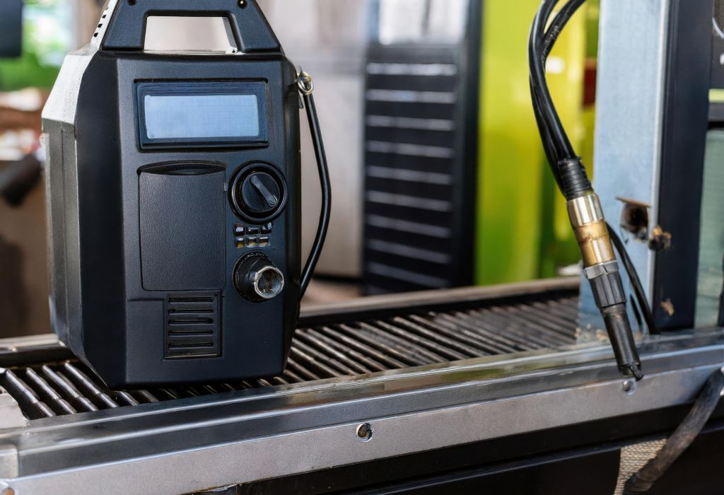
Every TIG welding machine features specific connector types designed to handle power, gas, and control signals safely.
Knowing these connections and their functions is crucial to avoid miswiring, which can damage internal components or disrupt current flow.
The most common connector found in modern TIG welders is the DINSE connector.
It provides a secure twist-lock mechanism for both the torch and the ground cable, ensuring a tight electrical connection.
DINSE connectors are often color-coded or labeled with polarity symbols to help users identify the correct terminal for DC or AC setups.
Another popular type is the Euro connector, commonly used in combination machines or advanced TIG systems.
It integrates the gas, current, and sometimes control lines into a single plug for quicker installation.
This reduces clutter and simplifies setup while ensuring proper gas sealing and contact alignment.
For foot pedals or hand controls, TIG welders often use multi-pin connectors such as 5-pin or 7-pin plugs.
Each pin corresponds to a function like trigger signal, amperage control, or remote enable.
It’s vital to check the manufacturer’s wiring diagram before connecting third-party pedals, as pin layouts differ between brands.
Misaligning these pins or forcing the connector can cause short circuits or disable amperage control.
Always inspect the plug orientation and gently tighten the locking ring once aligned.
If you’re setting up a high-frequency start system, proper cable shielding is critical.
Use insulated and shielded control cables to prevent electrical interference that could disrupt arc initiation.
Professional TIG welders also pay attention to strain relief and cable protection.
Ensure that no connector bears excessive tension or bends sharply near the plug.
Adding protective sleeves or cable guards can prevent fraying and extend component life.
Understanding these wiring standards not only ensures a successful TIG machine connection but also improves safety, reliability, and long-term equipment performance.
By mastering connector types and their proper usage, you’re already halfway to achieving a perfect TIG setup.
Best Practices for Cable Routing and Strain Relief
After connecting all essential components, proper cable management becomes the key to maintaining a reliable and long-lasting TIG welding setup.
Poor cable routing can lead to interference, overheating, or premature wear that affects both weld quality and operator safety.
Start by laying out all cables and hoses before you begin welding.
Ensure that the torch lead, ground cable, and gas hose follow separate paths to prevent tangling and electromagnetic interference.
When power cables and control lines overlap, they can generate unwanted magnetic noise, disrupting arc stability and foot pedal responsiveness.
Avoid sharp bends or tight loops in the cables.
Every welding cable has a minimum bend radius—exceeding it can weaken the conductor strands and damage the insulation.
Keep cables at gentle curves and secured loosely with non-conductive clips or cable ties.
Proper strain relief is another critical aspect of setup.
The goal is to eliminate tension where the cable meets the connector or terminal.
Use factory-supplied strain relief boots or install additional rubber sleeves to support heavier cables and prevent stress at the joints.
Keep the gas hose away from heat sources, sparks, and sharp edges.
Even a small nick can lead to leaks or fluctuating gas pressure that affects shielding quality.
If possible, use a cable cover or conduit to bundle the torch and gas hose together for smoother movement and extra protection.
Regularly inspect connection points for signs of chafing or exposed wires.
Clean any buildup of dust, metal debris, or oil around connectors using a dry cloth.
This simple maintenance step helps maintain strong electrical contact and consistent amperage flow.
Finally, ensure cables do not create tripping hazards in your workspace.
Secure them along walls or the floor using protective mats or cable channels.
Adopting these best practices for cable routing and strain relief keeps your TIG welding machine setup safe, efficient, and professional.
It not only enhances weld performance but also extends the service life of your equipment.
Verification and Testing After Connection
Once all connections are complete, it’s essential to verify that the TIG welding machine is functioning correctly before striking an arc.
This stage ensures that every electrical, gas, and control link performs as expected under normal operating conditions.
Begin by checking gas flow.
Open the cylinder valve slowly and observe the regulator’s gauge to confirm consistent pressure.
Activate the gas test function if your machine has one, or briefly press the pedal to allow gas flow through the torch.
Listen for smooth, steady airflow—uneven sound or bubbling often indicates a leak or restriction.
Next, inspect the power connections.
Confirm that the torch and ground clamps are secure and that terminals are clean from oxidation.
Loose connections may cause voltage drops, leading to weak or erratic arcs.
With the machine still idle, verify the remote control or foot pedal function.
Press the pedal slightly and check if the current reading on the display increases proportionally.
This confirms that the control signal is properly calibrated and responsive.
Perform a continuity test using a multimeter to ensure there are no breaks in the cable circuits.
Check between the torch connector, work clamp, and machine outputs.
Consistent readings indicate a solid electrical path.
Before welding, perform a trial arc on scrap metal using low amperage.
Observe the arc initiation, stability, and gas shielding.
A clean, quiet start and smooth bead confirm that the setup is correct.
Finally, double-check all connections after the first weld.
Vibration, heat, or movement can loosen fittings or shift cables.
Periodic inspections throughout the day help maintain reliable performance.
Testing after setup ensures every component in the TIG welding machine connection works safely and efficiently, setting the foundation for consistent, high-quality welds.
Advanced and Future Trends in TIG Connections

As welding technology evolves, the way TIG machines connect and communicate is becoming increasingly advanced.
Modern systems now integrate smart electronics, digital sensors, and wireless control options to enhance efficiency and precision.
One major advancement is digital data logging.
High-end TIG welders now record voltage, amperage, and gas flow data in real time.
This feature helps operators analyze weld consistency, track performance trends, and comply with strict quality control standards in industries like aerospace and shipbuilding.
Wireless foot pedals and remote controls are also transforming how welders interact with their machines.
These devices eliminate cable clutter and reduce tripping hazards while maintaining responsive current control.
Some advanced models even use Bluetooth encryption for secure, interference-free operation.
Quick-disconnect torch systems have simplified machine setup dramatically.
They allow welders to switch torches, gas hoses, or cables in seconds without reconfiguring fittings.
This innovation improves productivity, especially in multi-process or shared work environments.
Another trend is AI-assisted welding systems.
Artificial intelligence and sensor-based monitoring adjust voltage, gas flow, and current automatically in real time.
According to ResearchGate, automated monitoring can improve weld accuracy by up to 25%, reducing rework and material waste (ResearchGate.net).
Smart connectors are emerging as well.
These feature built-in temperature sensors and diagnostic chips that alert users to overheating or connection faults.
Some systems can even send maintenance alerts directly to mobile apps or control panels.
As the industry shifts toward automation and digital integration, welders who understand both traditional and advanced connection methods gain a significant advantage.
Mastering how to connect TIG welding machine with these modern innovations ensures not only stronger welds but also safer, more efficient operations in the years ahead.
Conclusion
A perfect TIG weld begins long before the first arc is struck.
It starts with a precise, well-organized connection of every cable, hose, and control on the welding machine.
Learning how to connect TIG welding machine the right way ensures a stable current flow, proper gas shielding, and consistent arc performance.
It also eliminates the most common problems—such as voltage drops, polarity mistakes, or gas leaks—that compromise weld quality.
From understanding each component’s role to following the correct connection sequence, every step contributes to safety and precision.
Inspecting cables, securing the ground clamp, verifying gas flow, and testing controls are not optional steps—they are essential habits of a skilled professional.
Proper connections also extend the life of both the machine and its accessories.
A clean, tight, and organized setup reduces heat buildup, prevents wear, and minimizes costly repairs.
According to Lincoln Electric, regular maintenance and connection checks can increase welding system longevity by up to 40% (LincolnElectric.com).
As TIG technology advances with digital controls and wireless systems, understanding these fundamentals remains the foundation of quality welding.
Every experienced welder knows that precision begins with preparation—and that starts with connecting the machine correctly.

I’m Darrell Julian, the founder, lead writer, and hands-on welding enthusiast behind ArcWeldingPro.com. With more than 15 years of real-world welding experience, I created this platform to share what I’ve learned in the field, in the shop, and in the heat of the arc.

