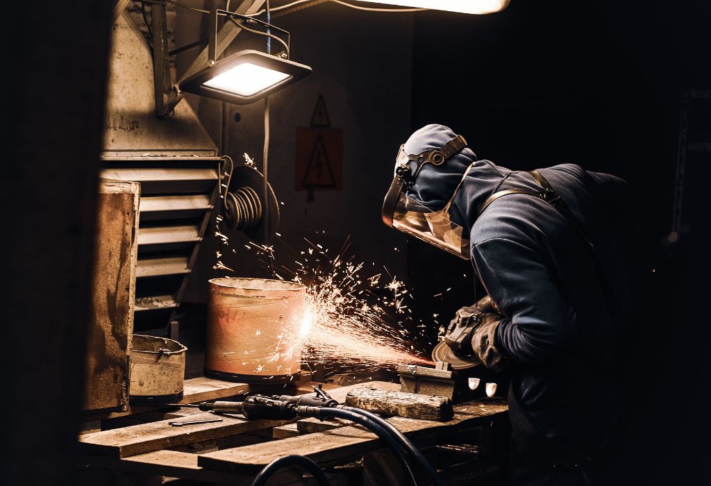
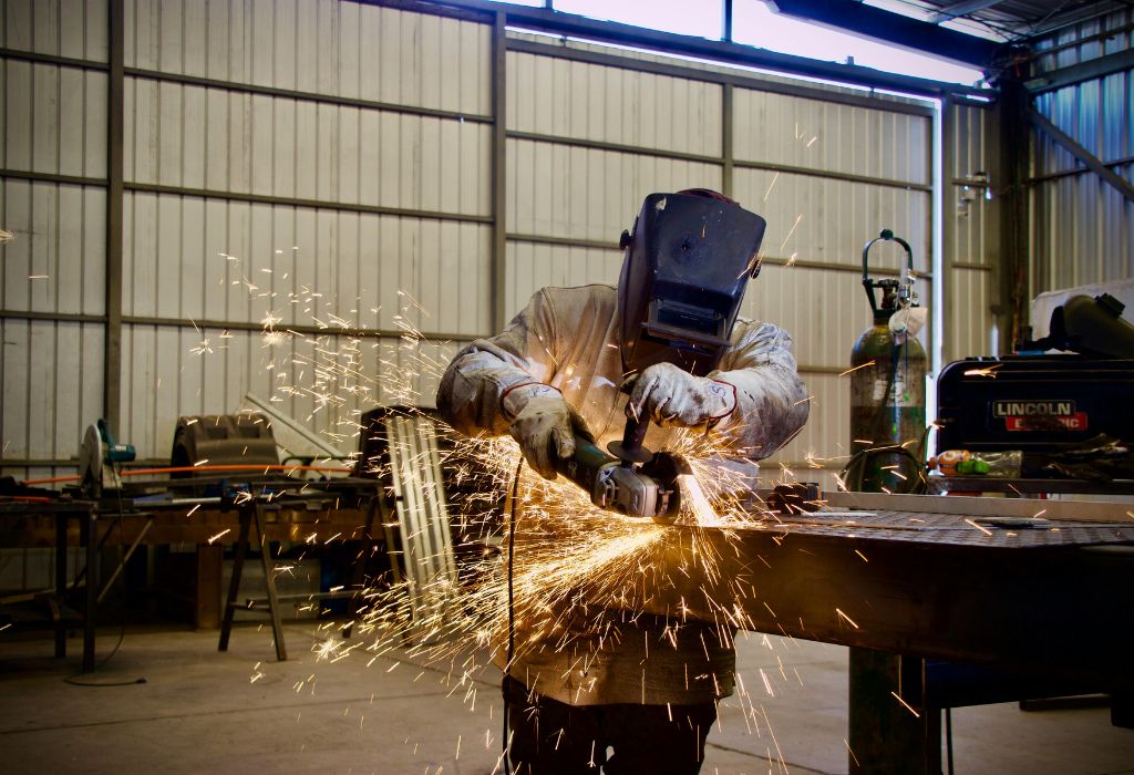
A welder stands in front of a MIG machine, puzzled by uneven beads and random spatter across the metal.
The settings look fine, yet the results are far from professional.
Many beginners face the same frustration after buying their first MIG welder.
The machine promises clean, efficient welds, but without the right setup, it can create weak joints, poor fusion, and messy finishes.
Improper setup is one of the most common causes of welding defects.
According to the American Welding Society, up to 40% of weld quality issues stem from incorrect voltage, wire feed, or gas settings source.
That means even a small adjustment in wire speed or polarity can transform a rough bead into a perfect one.
The curiosity lies in how a few dials and measurements determine the strength and appearance of every weld.
Understanding voltage, wire feed speed, and gas flow is not just about theory.
It is the difference between frustration and flawless results.
Professionals know that mastering how to set up a MIG welding machine is the foundation of consistent, clean, and strong welds.
A properly tuned setup ensures optimal penetration, reduced spatter, and a signature “frying bacon” sound that every welder aims for.
Understanding MIG Welding & Setup Basics
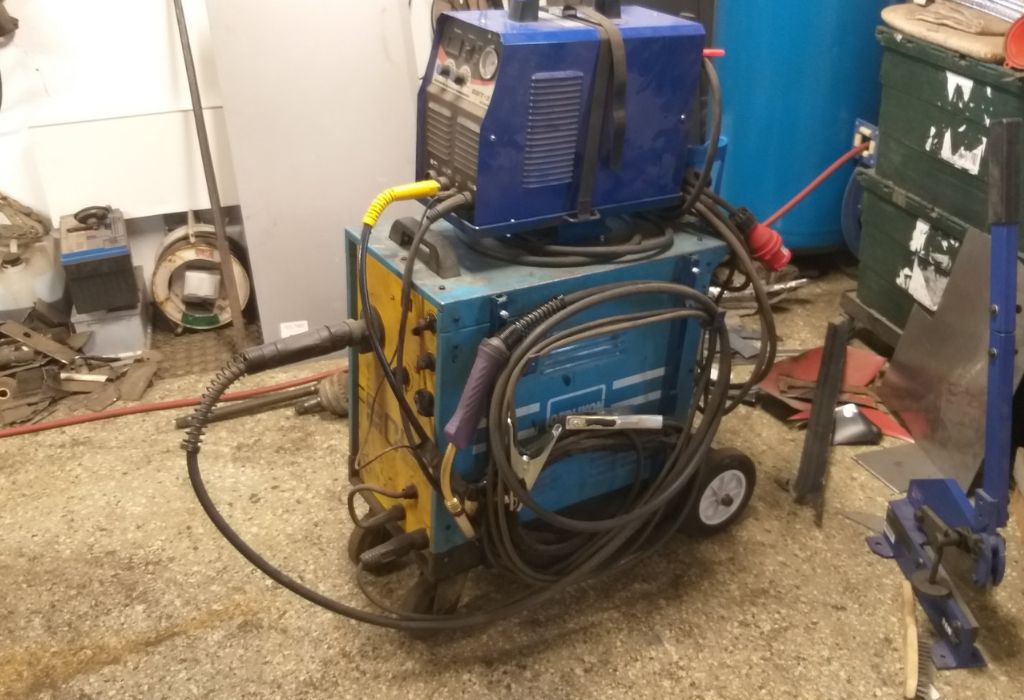
MIG welding, also known as Gas Metal Arc Welding (GMAW), is one of the most widely used processes in fabrication and repair work.
It relies on a continuous wire electrode fed through a welding gun, creating an electric arc that melts the base and filler metals together.
This process is admired for its speed, precision, and clean results.
When configured correctly, it produces smooth beads with minimal spatter, making it ideal for both professionals and beginners.
The setup, however, determines everything.
Incorrect voltage, wire feed speed, or gas flow can cause burn-through, porosity, and uneven penetration.
A machine that looks perfectly fine on the outside can produce inconsistent results if the internal parameters are not balanced.
According to Miller Electric, the right MIG welding setup can increase weld efficiency by over 30% when compared to improper calibration source.
That means every adjustment you make has a direct impact on productivity and weld quality.
The essence of mastering how to set up a MIG welding machine lies in understanding how these variables interact—voltage controls arc length, wire feed affects amperage, and gas shields the weld from atmospheric contamination.
When these three are aligned, the arc becomes stable, penetration becomes uniform, and bead appearance improves dramatically.
What is MIG (GMAW)?
It is a welding process that uses a continuously fed wire and shielding gas to create an electric arc for joining metals.
Why is setup critical for bead quality?
Proper setup ensures stable arc performance, consistent penetration, and minimal weld defects like porosity or spatter.
Which metals can be MIG welded?
MIG welding works well with mild steel, stainless steel, and aluminum when the correct wire and gas combination is used.
What are common weld defects from bad setup?
Improper setup can lead to spatter, weak fusion, burn-through, and rough bead texture.
What is duty cycle and why does it matter?
The duty cycle indicates how long a welding machine can run at a given current before overheating, helping prevent equipment damage.
Safety & Equipment Checklist Before Setup
Before touching the power switch or loading wire, it is essential to create a safe welding environment.
Safety preparation ensures not only personal protection but also the consistency and reliability of every weld.
MIG welding involves high current, pressurized gas, and ultraviolet radiation, all of which pose risks if handled carelessly.
Even a minor gas leak or damaged cable can lead to severe accidents or poor arc stability during operation.
A proper setup begins with inspection.
Cables, connectors, ground clamps, and the gas regulator must be checked for any wear, cracks, or leaks before starting.
Clean and well-maintained equipment directly contributes to better conductivity, arc control, and weld penetration.
According to OSHA statistics, over 60% of welding-related injuries occur due to improper PPE or poor equipment inspection source.
That makes preparation a critical step rather than an optional one.
Welders should also ensure proper ventilation and avoid confined spaces filled with fumes or flammable vapors.
The safest environment is one that prevents problems before the first spark is struck.
What PPE is essential?
A welding helmet with an auto-darkening filter, flame-resistant gloves, leather jacket or sleeves, safety boots, and respirator when required.
How to check gas hoses and leaks?
Apply a soap-and-water solution on joints and fittings; bubbles indicate leaks that must be fixed before welding.
How to verify correct cable and plug rating?
Ensure that the plug and cable match the machine’s amperage capacity and are rated for industrial use.
Why ground the machine properly?
A solid ground connection prevents arc instability, voltage fluctuations, and potential electric shock hazards.
When to purge lines or bleed the regulator?
Always after opening the cylinder valve; this clears moisture and contaminants from the line before welding begins.
Basic Machine Setup Steps
Once the safety checks are complete, the next stage is preparing the MIG welder for operation.
Each setup step plays a role in ensuring consistent wire feed, stable arc, and clean weld formation.
Start by connecting the machine to the proper power source according to its voltage rating.
Using the wrong power supply can cause inconsistent arc behavior or even internal circuit damage.
Mount the wire spool securely on the hub and check its rotation direction.
The wire should unwind smoothly toward the drive rolls without friction or slippage.
Thread the wire through the feed mechanism and into the welding gun liner.
Ensure the drive roll tension is tight enough to push the wire evenly but not so tight that it crushes or deforms it.
Next, confirm that polarity is set correctly.
Most MIG setups require DC Electrode Positive (DCEP) for solid wire, which promotes better penetration and bead shape.
Incorrect polarity can instantly cause poor fusion or excessive spatter.
Attach the gas cylinder and connect the regulator.
Open the valve slowly and set the flow rate between 15–20 CFH for most mild steel applications.
Listen for leaks and ensure consistent flow before welding.
Finally, adjust initial machine parameters—voltage and wire feed speed—based on material thickness.
As a rule of thumb, one amp of welding current is required per 0.001 inch of metal thickness.
This starting point helps fine-tune the balance between penetration and bead appearance.
How to mount the wire spool?
Place the spool on the hub, ensure smooth rotation direction, and secure the tension knob to prevent wire backlash.
How to thread wire through drive rolls and torch?
Feed the wire through the inlet guide, drive rolls, liner, and out through the contact tip until it exits the gun nozzle.
Which polarity is typically used?
Most MIG welding with solid wire uses DCEP (Direct Current Electrode Positive) for better arc stability and penetration.
How to open and regulate shielding gas?
Open the cylinder valve fully, adjust regulator pressure, and set flow rate between 15–20 CFH depending on conditions.
What starting voltage and wire feed speed to choose?
Refer to the machine’s chart or manual; typically, 18–20 volts and 250–300 in/min for 1/8-inch steel provide a balanced start.
Fine-Tuning Voltage, Wire Feed & Travel Speed
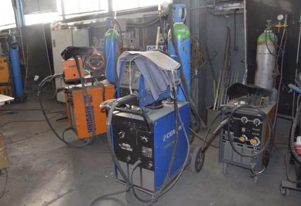
After completing the basic setup, the next step is fine-tuning the MIG welder’s performance.
This stage determines how clean, smooth, and strong your final welds will be.
Voltage, wire feed speed, and travel speed work together to shape the bead and control penetration.
Even a small change in one setting can make the difference between a flawless weld and a messy, uneven line.
Start by adjusting the voltage to stabilize the arc.
Low voltage often causes a short, erratic arc with stubbing, while high voltage leads to excessive spatter and poor bead control.
Finding the right balance gives a consistent sizzle and a uniform bead profile.
Next, match the wire feed speed with voltage.
If the wire feed is too fast, it will push into the puddle and create uneven buildup.
Too slow, and the wire will melt back into the tip, causing burn-back or lack of penetration.
Travel speed plays an equally important role.
Moving too quickly results in narrow beads and weak fusion, while moving too slowly can overheat the metal and distort the joint.
The goal is a rhythm that maintains a stable puddle and even ripple pattern.
According to ESAB University, proper voltage and wire feed calibration can reduce weld spatter by up to 25% source.
This improvement not only saves time but also ensures cleaner results and less grinding.
How to balance voltage and wire feed?
Increase voltage when raising wire feed speed to keep the arc length consistent and prevent stubbing.
What happens if voltage is too low or high?
Low voltage causes poor fusion and spatter; high voltage produces wide, flat beads and blow-through.
What is optimal travel speed?
A steady pace that keeps the puddle flowing smoothly without undercutting or excessive buildup.
How to observe bead cues for adjustment?
A tight, uniform ripple pattern and smooth sound indicate correct parameters.
What is stickout (electrode extension)?
Maintain 3/8″ to 1/2″ of stickout; longer stickout lowers amperage and reduces penetration.
Choosing Wire, Gas & Consumables
Selecting the right wire, shielding gas, and consumables is crucial for achieving consistent weld quality.
These elements determine the arc’s stability, penetration depth, and the smoothness of the final bead.
Different materials and projects demand unique wire and gas combinations.
For instance, mild steel requires a different setup compared to stainless steel or aluminum, and each responds differently to variations in wire composition and gas flow.
Solid MIG wire, such as ER70S-6, is the most common for mild steel because it provides excellent feedability and smooth arcs.
For aluminum, ER4043 or ER5356 works best with 100% Argon gas, while stainless steel benefits from tri-mix or 98% Argon/2% CO₂ blends.
The gas you choose directly impacts arc characteristics and spatter control.
Wire diameter also influences current levels and penetration.
Thicker wires handle more amperage but may struggle with thin materials, while thinner wires offer better control and precision for light fabrication work.
Contact tips, nozzles, and liners should always match wire size and type.
A mismatch can cause poor conductivity, wire jams, or erratic feeding.
According to WeldGuru, using the correct consumables can improve feed consistency by up to 40% source.
Keeping consumables clean is equally important.
Spatter buildup in the nozzle or dirt in the liner restricts gas flow, creating porosity or unstable arcs.
Regular maintenance ensures smooth gas delivery and consistent weld quality.
Which wire type is best for steel vs aluminum?
Use ER70S-6 solid wire for steel and ER4043 or ER5356 for aluminum applications.
What wire diameters suit which amperage range?
.023″ wire is ideal for thin metals, .030″ for medium thickness, and .035″ or .045″ for heavy sections.
What gas mixtures are most common?
75% Argon / 25% CO₂ for steel, 100% Argon for aluminum, and tri-mix for stainless steel.
How to choose the right contact tip and nozzle size?
Match the contact tip to the wire diameter and ensure nozzle clearance allows steady gas flow.
How often should consumables be cleaned or replaced?
Inspect after every few hours of welding; replace nozzles, tips, or liners showing wear, blockage, or oxidation.
Testing Setup & Making Test Beads
Before starting on an actual workpiece, running test welds is essential to confirm that all settings are properly balanced.
Testing allows you to evaluate penetration, bead shape, and gas coverage under controlled conditions.
Begin by preparing a clean scrap piece of the same material and thickness as your main project.
Clamp it securely and ensure a good ground connection to maintain arc stability.
Trigger the gun briefly to confirm smooth wire feed and gas flow.
If you hear popping, stuttering, or excessive spatter, adjustments are needed in voltage or wire feed speed.
Run short test beads at varying voltages and travel speeds to find the combination that produces consistent results.
Look closely at the bead shape and ripples; they reveal whether the arc is stable or if changes are required.
According to Lincoln Electric, test welding before production can reduce rework time by up to 35% source.
Testing not only prevents wasted material but also gives you confidence in the final setup.
A good test weld should show even width, smooth edges, and visible penetration on the backside of the joint.
If there is excessive buildup, undercut, or inconsistent pattern, fine-tune your parameters until the results are repeatable.
How to start a test weld?
Pull the trigger to start gas flow, extend wire slightly, and strike the arc on the scrap metal surface.
What bead features indicate settings need change?
A narrow or high bead shows low voltage; excessive spatter or flat bead indicates voltage too high.
When to increase or decrease wire feed?
Increase wire feed if the bead is narrow or uneven; decrease if the wire is pushing into the puddle.
How to adjust voltage after a bead test?
If the arc feels short or stubbing, raise voltage slightly; if it sounds too harsh, lower voltage a bit.
How many test passes before final welding?
Perform at least two or three test beads at different settings to identify the most stable configuration.
Troubleshooting & Common Pitfalls
Even with a perfect setup, welding issues can still arise.
Understanding the most common problems and how to fix them quickly can save hours of wasted time and prevent costly material loss.
Porosity, excessive spatter, and wire feeding issues are among the most frequent challenges.
Each one often points to an underlying problem in gas flow, voltage balance, or equipment condition.
If welds show small holes or bubbles, the issue is usually poor shielding gas coverage.
Check for leaks, low flow rate, or drafts around the workspace that disrupt gas protection.
Excessive spatter is another sign that parameters are off.
Too much voltage or improper wire feed can cause molten droplets to scatter across the metal, leading to messy beads and cleanup work.
A lack of fusion or cold lap often results from moving too fast or using insufficient current.
To fix it, reduce travel speed slightly and verify proper wire feed speed for material thickness.
According to TWI Global, over 50% of weld quality defects come from incorrect setup or poor maintenance source.
This makes troubleshooting not just reactive but an essential skill for long-term efficiency.
A systematic approach—observe, identify, and adjust—will keep your MIG welding machine performing at its best.
Most problems can be solved by verifying polarity, gas flow, and wire feed alignment before restarting.
Why is there porosity in the weld?
Porosity happens due to gas leaks, low flow rate, or contaminants like rust, oil, or moisture on the base metal.
What causes excessive spatter?
Incorrect voltage, wrong gas mix, or dirty metal surface can create unstable arcs and heavy spatter.
Why is there lack of fusion or cold lap?
It results from low amperage, long stickout, or moving the gun too quickly across the joint.
Why does the wire birdnest or tangle?
Improper drive roll tension, kinked liner, or worn-out feed components cause wire jams or nesting.
Why does the welder cut out or overheat?
The duty cycle may have been exceeded, or there’s a voltage drop from an undersized extension cable.
Setup for Different Material Types & Positions
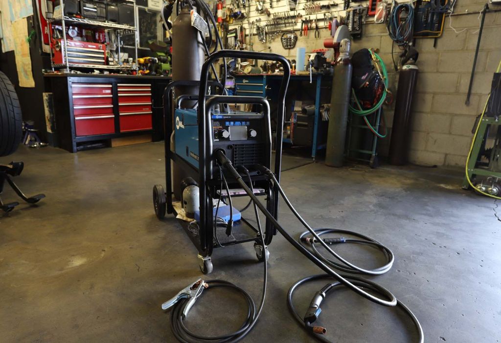
Every metal type and welding position reacts differently to heat, gas flow, and wire speed.
Adjusting your MIG welding machine to match these variables ensures strong joints and consistent bead profiles across all conditions.
For thin materials, use lower voltage and wire feed speeds to prevent burn-through.
A shorter stickout and steady travel speed help maintain control of the puddle and reduce distortion.
When welding thicker plates, increase amperage and voltage for deeper penetration.
You may need to bevel the edges and make multiple passes to achieve full fusion.
Vertical and overhead welding require special care.
Reducing wire feed and voltage helps control the molten metal, preventing it from dripping or sagging.
Using a weaving or upward technique can also stabilize the arc and improve bead formation.
For aluminum welding, always use 100% Argon gas and a spool gun or push feeder for proper wire delivery.
Maintain a clean surface and slightly longer stickout to prevent contamination and ensure strong fusion.
Stainless steel requires controlled heat input to avoid warping or color distortion.
A tri-mix gas (90% Helium, 7.5% Argon, 2.5% CO₂) can enhance arc stability and minimize oxidation during welding.
According to Fabricator.com, adjusting parameters by material type can increase joint integrity by up to 25% source.
Tailoring settings for each situation is the key to mastering MIG welding versatility.
How to set up for thin gauge metal?
Use low voltage, short stickout, and faster travel to prevent burn-through.
How to adjust for thick plate?
Increase voltage and wire feed, bevel edges, and apply multiple passes for full penetration.
What changes for vertical or overhead welding?
Reduce heat input, lower wire speed, and use a steady upward or side-to-side motion.
How to adapt for aluminum MIG welding?
Use 100% Argon, a spool gun, and ensure clean metal for contamination-free welds.
What about welding stainless steel?
Use a tri-mix gas blend and limit heat exposure to maintain color and structural integrity.
Conclusion
Setting up a MIG welding machine the right way is the foundation of every strong, clean, and professional weld.
From understanding voltage and wire feed to balancing gas flow and travel speed, each element works together to define bead quality and overall performance.
A well-configured setup eliminates spatter, improves penetration, and reduces rework time significantly.
The difference between a messy weld and a flawless bead often comes down to a few precise adjustments made during setup.
By following each step carefully—safety checks, fine-tuning, and proper material calibration—you not only protect your equipment but also build the consistency and control that define expert craftsmanship.
According to industry research, a properly tuned MIG system can boost productivity by more than 30% source.
Ultimately, learning how to set up a MIG welding machine is not just about turning dials.
It’s about understanding how small details transform the outcome of every weld.
Start with patience, test your setup, and let precision lead the way toward perfect, professional-grade beads.

I’m Darrell Julian, the founder, lead writer, and hands-on welding enthusiast behind ArcWeldingPro.com. With more than 15 years of real-world welding experience, I created this platform to share what I’ve learned in the field, in the shop, and in the heat of the arc.

