Whether you’re a DIYer in your garage, a hobbyist building custom projects, a pro on a construction site, or a student learning the trade, you’ve likely heard about RT vs UT weld inspection. These non-destructive testing (NDT) methods are critical for ensuring your welds are strong, safe, and up to code. I’ve spent years welding everything from structural steel to pipelines, and I’ve seen how proper inspection can make or break a project.
Weld integrity isn’t just about passing a test—it’s about safety, durability, and taking pride in your work. Let’s dive into RT (Radiographic Testing) and UT (Ultrasonic Testing), break them down, and figure out which one’s right for your job.

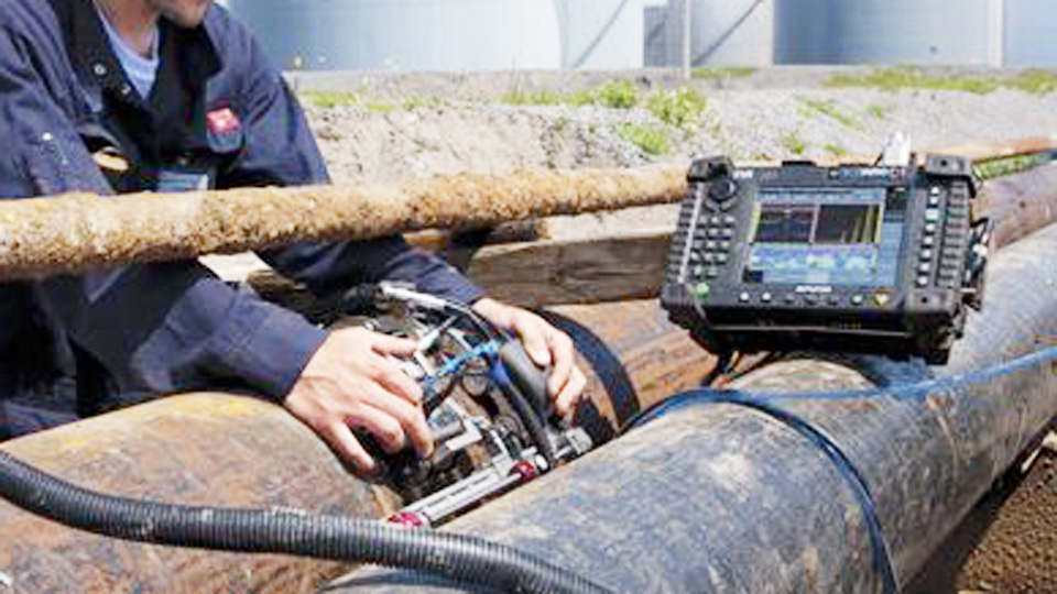
Image by olympus-ims
Why Weld Inspection Is a Big Deal
A weld isn’t just a joint; it’s the backbone of structures like bridges, pressure vessels, or even your custom BBQ pit. A weak weld can lead to cracks, leaks, or catastrophic failures—nobody wants that. I once saw a rookie skip inspection on a small fabrication job, only to have a crack show up during load testing. Hours of rework could’ve been avoided with proper NDT.
RT and UT are your best tools for spotting hidden flaws like porosity, cracks, or inclusions without destroying the weld. Choosing between them depends on your project’s needs, budget, and safety requirements. Let’s explore both so you can make smart choices.
Understanding Radiographic Testing (RT)
Radiographic Testing, or RT, is like giving your weld an X-ray. It uses X-rays or gamma rays to penetrate metal and create an image on film or a digital detector. The image reveals what’s inside the weld—cracks, voids, or inclusions show up as lighter or darker spots because they block radiation differently than solid metal.
How RT Works in the Shop
Imagine you’ve just welded a thick steel plate for a pressure vessel. With RT, you place a radiation source (like an X-ray tube or a gamma ray emitter) on one side of the weld and a film or detector on the other. The radiation passes through, and the image shows the weld’s internal structure. I’ve watched RT techs on pipeline jobs carefully align the source to capture a clear shot of a butt weld. It’s a precise process, but it takes time and a controlled setup.
When to Choose RT
RT is your go-to when you need a permanent, visual record of the weld. It’s perfect for complex welds like pipe joints or multi-pass welds on thick materials. Industries like oil and gas, aerospace, and construction rely on RT because it’s great for spotting volumetric flaws—think porosity or slag inclusions. If you’re working to ASME or API standards, RT is often required because inspectors can review the images later. I’ve used RT on high-pressure pipeline welds where a clear film was non-negotiable for code compliance.
Practical RT Tips for Welders
- Prep the Weld: Clean off slag, spatter, and grease. I once saw an RT image ruined by surface oil—don’t let that happen. A clean weld ensures a clear image.
- Safety Protocols: RT uses radiation, so you need shields, restricted zones, and certified techs. I’ve cleared entire job sites for RT—follow OSHA and NRC rules to stay safe.
- Equipment Check: Pros, ensure your X-ray tube or gamma source is calibrated. A weak source gives blurry images, wasting everyone’s time.
- Common Mistake: Misaligned source and detector. If the angle’s off, you’ll miss flaws. Always double-check your setup geometry.
RT Pros and Cons
| Pros | Cons |
|---|---|
| Permanent visual record | Radiation safety risks |
| Detects volumetric flaws | Expensive equipment |
| Ideal for complex welds | Slow (film processing) |
| Works on thick materials | Can’t measure defect depth |
Understanding Ultrasonic Testing (UT)
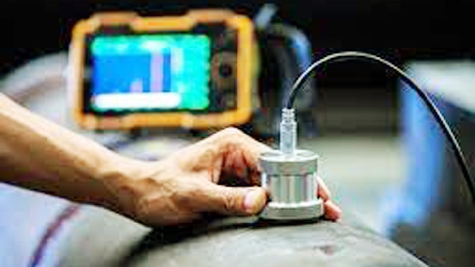
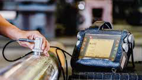
Ultrasonic Testing, or UT, is like sonar for your welds. It uses high-frequency sound waves to detect flaws. A transducer sends sound into the weld, and when the waves hit a defect or the back of the material, they bounce back. The reflected signals show up on a screen, revealing the size, location, and depth of any issues.
How UT Works on the Job
Picture yourself inspecting a long seam weld on a structural beam. You apply a couplant (like gel) to the weld surface to help sound waves travel from the transducer into the metal. The transducer sends pulses, and the echoes appear as peaks on a screen. By analyzing these, you can spot cracks, lack of fusion, or porosity. I’ve used UT on fast-paced field jobs where we needed results on the spot—it’s quick and effective.
When to Choose UT
UT is ideal for quick inspections, especially when you only have access to one side of the weld. It’s great for detecting planar flaws like cracks or lack of fusion and can measure defect depth, unlike RT. Industries like manufacturing, automotive, and structural steel love UT for its portability and safety (no radiation). For DIYers or small shops, UT equipment is more accessible than RT, though it takes practice to master.
Practical UT Tips for Welders
- Surface Prep: Grind the weld smooth for good sound transmission. I’ve seen UT fail because of rough welds—take time to prep right.
- Calibration: Match your transducer to the material’s thickness and type. I once miscalibrated on stainless steel and got bad readings. Always use a reference block.
- Couplant Application: Apply a thin, even layer of couplant. Too much can distort signals, too little reduces contact.
- Common Mistake: Scanning too fast. Move the transducer slowly to catch all echoes. I’ve found tiny cracks by being patient that others missed.
UT Pros and Cons
| Pros | Cons |
|---|---|
| No radiation, safer | Needs skilled operators |
| Real-time results | Surface prep is critical |
| Measures defect depth | Less effective for complex shapes |
| Portable and affordable | No permanent visual record |
RT vs UT: Breaking Down the Differences
Let’s compare RT and UT head-to-head to help you choose the right method for your welds. Whether you’re building a trailer in your shop or inspecting a refinery component, these differences matter.
Technique and Results
RT produces a visual image, like a photo of the weld’s insides, making it easy to spot porosity or inclusions. UT gives you data—peaks or patterns on a screen—that show defect location and depth. If you prefer visuals, RT’s images are intuitive, but UT’s real-time feedback is great for quick decisions. I’ve used both on jobs where RT caught gas pockets, but UT found cracks RT missed.
Safety First
RT’s radiation requires strict safety measures—think lead shields and restricted areas. I’ve had to stop work on sites for RT setups, which can slow things down. UT is radiation-free, making it safer and easier for busy shops or field work. For DIYers, UT’s safety makes it the better choice.
Cost and Portability
RT is expensive—think X-ray machines, gamma sources, and film costs, plus safety compliance. It’s also less portable, needing a controlled setup. UT gear, like a handheld flaw detector, is cheaper (starting at $2,000) and easy to carry. I’ve hauled UT equipment to remote sites with no hassle, while RT often requires a dedicated truck.
What They Detect
RT is king for volumetric flaws like porosity or slag. UT excels at planar flaws like cracks or lack of fusion and can measure their depth. I’ve seen welds pass RT but fail UT due to tiny cracks invisible on film. Conversely, minor porosity caught by RT might not fail UT if it’s within code limits.
Speed of Inspection
UT is faster, giving instant results as you scan. RT involves film processing or digital review, which can take hours. On a tight job, UT’s speed has saved me when we needed to keep things moving.
Material and Weld Considerations
RT handles thick materials and complex welds, like multi-pass pipe joints, with ease. UT is versatile but can struggle with very thick sections or materials like composites that scatter sound. For thin steel plates, both work, but UT’s speed often wins.
How to Choose Between RT and UT
Picking the right method depends on your project. Here are some scenarios I’ve faced that might match your situation.
Scenario 1: Pipeline Welds
You’re welding a 16-inch pipeline to API 1104. The code often requires RT for its visual record and ability to spot porosity, common in pipe welds. You set up an X-ray crawler, clear the site, and shoot the welds. If speed or single-side access is an issue, UT with a phased array can work just as well for cracks, saving time.
Scenario 2: Structural Steel
You’re fabricating beams for a building under AWS D1.1. UT is preferred for its portability and crack detection in fillet welds. You calibrate a handheld UT device for A36 steel and scan on-site. For critical joints, RT might be added for a visual record if the client demands it.
Scenario 3: DIY Fabrication
You’re a hobbyist welding a custom trailer frame. RT is too complex and costly for your shop. UT is more realistic if you invest in a basic flaw detector and practice on scrap. Stick to simple butt welds for easier scanning, and you’ll ensure your trailer’s welds are road-ready.
Decision Factors
- Material Type: RT works on thick, dense metals; UT is better for thinner sections or aluminum.
- Defect Priority: Porosity? Choose RT. Cracks? Go UT.
- Access: Single-side access favors UT; RT needs both sides.
- Budget: UT is cheaper and faster.
- Code Specs: ASME, AWS, or API codes may mandate one method.
- Safety Needs: UT’s radiation-free nature is a big plus.
Weld Prep and Settings for Inspection Success
Your weld quality directly affects RT and UT results. Here’s what I’ve learned from years of welding and inspection.
Preparing Your Weld
- Cleanliness: For RT, remove all slag and spatter. For UT, grind welds smooth to ensure good transducer contact. I once had a UT scan fail due to a rough weld—don’t skip grinding.
- Joint Design: Butt welds are easiest for both methods. Fillet welds can complicate RT due to angles—adjust the source carefully.
- Filler Selection: Use fillers like ER70S-6 for mild steel MIG to match the base metal. Mismatched fillers can cause UT signal issues due to different sound velocities.
Welding Machine Settings
- For RT: Consistent welds are key. For thin materials, use lower amperage (e.g., 90-120A for 1/8-inch steel with MIG) to avoid burn-through, which can look like porosity on RT images.
- For UT: Calibrate your transducer for the material. For 1/2-inch steel, a 5 MHz, 0-degree probe works well. Adjust gain to reduce noise but keep small defects visible.
Avoiding Common Mistakes
- RT Error: Poor film alignment. Misplace the film, and you’ll miss flaws. Fix: Use alignment markers and check twice.
- UT Error: Incorrect calibration. I’ve gotten false positives from bad settings. Fix: Calibrate on a reference block for your material.
- Both: Rushing prep. A clean, smooth weld saves headaches for both methods.
Meeting US Welding Codes
In the USA, codes like ASME Section VIII, AWS D1.1, and API 1104 govern weld inspections. These set rules for when to use RT or UT and define acceptable defect levels. For example, ASME is strict on porosity for pressure vessels, often favoring RT. AWS D1.1 leans toward UT for structural welds due to crack sensitivity. Always check your project’s code to avoid costly rework. I’ve had to redo welds after missing a code spec—learn from my mistake.
Using RT and UT Together
For critical jobs like nuclear components or high-pressure pipelines, I’ve seen shops combine RT and UT. RT catches porosity and inclusions, while UT pinpoints cracks and depths. This dual approach ensures nothing gets missed. If you’re a pro, talk to your NDT tech about combining methods for high-stakes welds. DIYers, this might be overkill, but it’s good to know for future projects.
Step-by-Step Guide to Preparing for Inspection
Here’s a quick guide to prep your welds for RT or UT, based on my shop experience:
- Clean the Weld: Remove slag, spatter, and grease with a wire brush or grinder. For UT, grind the weld smooth.
- Check Joint Design: Ensure the joint (butt, fillet, etc.) suits the inspection method. Butt welds are easiest.
- Select Filler: Match filler to base metal (e.g., E7018 for stick welding mild steel) to avoid inspection issues.
- Weld Consistently: Use stable settings (e.g., 120-150A for 1/4-inch steel with MIG) to minimize defects.
- Inspect Surface: For RT, ensure no surface flaws obscure the image. For UT, verify a smooth surface for transducer contact.
- Coordinate with NDT Tech: Confirm the method, setup, and code requirements before inspection begins.
Conclusion
You’re now ready to tackle RT vs UT weld inspection with confidence. Radiographic Testing gives you a clear, permanent image to spot porosity and inclusions, but it’s costly and involves radiation. Ultrasonic Testing is fast, safe, and ideal for finding cracks and measuring their depth, though it demands skill and prep. By considering your material, defect type, budget, and code requirements, you can choose the best method—or combine them—for welds that pass with flying colors.
FAQ
What’s the key difference between RT and UT weld inspection?
RT uses X-rays or gamma rays to create a visual image of the weld, great for porosity and inclusions. UT uses sound waves to detect flaws and measure depth, ideal for cracks. RT needs both sides of the weld, while UT works from one side.
Which method is best for finding cracks in welds?
UT is better for cracks, especially planar ones, because it measures depth and location accurately. RT can miss fine cracks if they align with the radiation path. For crack-sensitive welds, UT is the go-to.
Is RT or UT more affordable for small welding shops?
UT is more affordable, with cheaper equipment and faster inspections. RT’s high costs and radiation safety requirements make it less practical for small shops or DIYers.
Can DIY welders perform RT or UT themselves?
UT is more realistic for DIYers with training and a basic flaw detector ($2,000-$5,000). RT requires expensive gear and radiation certifications, making it impractical for home use. Get trained or hire a pro.
How do I prepare a weld for RT or UT?
Clean the weld of slag and spatter. For RT, ensure a grease-free surface. For UT, grind the weld smooth and apply a thin couplant layer. Proper prep ensures accurate results.

I’m Darrell Julian, the founder, lead writer, and hands-on welding enthusiast behind ArcWeldingPro.com. With more than 15 years of real-world welding experience, I created this platform to share what I’ve learned in the field, in the shop, and in the heat of the arc.


