In modern construction, manufacturing, and engineering projects, welding blueprints are like roadmaps guiding workers toward safe and accurate fabrication. Yet, for many beginners, the arrows, lines, triangles, and letters on these blueprints look like a foreign language.
According to the American Welding Society (AWS), a significant portion of weld quality issues in construction projects comes from blueprint misinterpretation. As industries embrace automation and high-precision manufacturing, the demand for welders who can read welding symbols has grown rapidly.
Welding symbols condense complex welding instructions into simple, standardized diagrams. They tell you what type of weld to use, where to apply it, its size, finish, and even the welding process required. A single symbol can communicate what might otherwise take several sentences of explanation.
This article provides a complete beginner’s guide to welding symbols and their meanings. We’ll break down each part of a welding symbol, explain different weld types like fillet and groove welds, and show you how to read blueprints with confidence. Real-world examples, diagrams, and visual charts will help make the learning process simple and practical.
By the end, you’ll be able to:
- Identify the basic parts of a welding symbol.
- Understand the meanings of common weld symbols on blueprints.
- Avoid costly mistakes caused by misreading welding instructions.
Whether you’re a welding student, apprentice, or construction professional, this guide will give you the knowledge you need to interpret welding symbols correctly and apply them in real projects.
Why Welding Symbols Matter in Modern Industry
Welding symbols play a critical role in ensuring accuracy, safety, and efficiency in industrial projects. A single mistake in interpreting weld requirements can lead to weak joints, structural failures, or costly rework.
In construction, welding symbols on blueprints specify exactly what type of weld to use, its size, and location on beams, columns, and bridges. This standardization prevents confusion between designers, engineers, and welders on-site.
The American Welding Society (AWS) and International Organization for Standardization (ISO) have developed global standards for welding symbols. These standards ensure that welders in the U.S., Europe, or Asia interpret the same symbol in the same way.
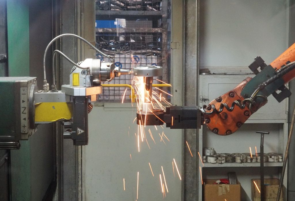
Manufacturing and automotive industries also rely heavily on welding symbols for mass production. Robots and automated welding systems use digital blueprints containing these symbols to perform precise, repeatable welds in high-volume environments.
In aerospace, energy, and oil & gas projects, welding symbols guarantee compliance with safety regulations. Properly executed welds based on standardized instructions reduce the risk of leaks, explosions, or mechanical failures.
Why are welding symbols used in blueprints?
They provide standardized instructions for weld type, size, and location to ensure consistency and quality.
Who creates welding standards worldwide?
Organizations like AWS (U.S.) and ISO (International) develop welding symbol standards.
Do all industries use the same welding symbols?
Yes, most industries follow AWS or ISO standards for consistency across global projects.
Can welding symbols improve project safety?
Yes, accurate interpretation reduces structural risks and ensures regulatory compliance.
Are welding symbols used in robotic welding systems?
Yes, automated systems rely on digital blueprints with standardized symbols for accuracy.
Basic Components of Welding Symbols
Welding symbols may look complicated at first, but they are built from a few simple components. Once you understand these parts, interpreting blueprints becomes much easier for beginners.
The Reference Line is the backbone of the welding symbol. All other elements like arrows, weld symbols, and additional notes are attached to this horizontal line.
The Arrow points to the exact location on the drawing where the weld must be made. Depending on the side it points to, the weld can be on the arrow side or the opposite side of the joint.
The Tail of the symbol is optional. It provides extra information such as welding processes, specifications, or standards like AWS or ISO codes.
The Weld Symbol itself is a small geometric shape placed on the reference line. Different shapes indicate different weld types, like fillet welds, groove welds, or plug welds.
Additional supplementary symbols like contour lines, finish symbols, or all-around indicators modify or clarify the welding requirements.
What is the reference line in a welding symbol?
It’s the main horizontal line where all elements like arrows and weld symbols attach.
What does the arrow indicate?
The arrow points to the exact location on the drawing where the weld should be applied.
Are welding symbol tails always required?
No, tails are optional and only used for extra notes like process codes or standards.
What do different weld symbols represent?
They indicate specific weld types such as fillet, groove, plug, or spot welds.
Do supplementary symbols change the weld requirements?
Yes, they specify details like weld contour, finishing method, or field weld conditions.
Types of Welding Symbols and Their Meanings
Different welding symbols represent different weld types. Understanding these symbols helps beginners read blueprints accurately and choose the right welding method for each project.
Below are the most common welding symbols used across construction, manufacturing, automotive, and aerospace industries.
Fillet Weld Symbols
Fillet welds join two metal pieces at a right angle, like in T-joints or lap joints. The triangular symbol on blueprints represents fillet welds.
They are widely used in construction for beams, frames, and heavy equipment manufacturing.
Groove Weld Symbols
Groove welds join two metal pieces in the same plane with a gap between them. The shape of the groove (V, U, J, or bevel) determines the symbol used.
They are common in pipelines, pressure vessels, and structural applications requiring full penetration.
Plug and Slot Weld Symbols
These welds join overlapping pieces by filling holes (plug welds) or elongated slots (slot welds) in one piece to bond it to the base material below.
Automotive industries often use them in vehicle frames and panels for strength and durability.
Spot and Seam Weld Symbols
Spot welds create circular welds at specific points, while seam welds produce continuous welds along a joint.
Both are widely used in sheet metal fabrication, HVAC systems, and car manufacturing.
Surfacing Weld Symbols
Surfacing welds deposit material on a surface to increase thickness or provide wear resistance.
They are often used in mining, construction equipment, and heavy machinery repair.
Back and Backing Weld Symbols
Back welds are applied after the main weld on the opposite side to ensure full penetration.
Backing welds use a backing material to support molten metal during welding, preventing leaks or incomplete fusion.
What is the most common weld symbol for beginners to learn first?
The fillet weld symbol, as it’s used in most structural and fabrication projects.
Where are groove weld symbols mostly used?
In pipelines, pressure vessels, and structural joints requiring strong, full-penetration welds.
What do spot weld symbols represent?
They indicate circular welds used in automotive and sheet metal projects.
Why are surfacing welds important?
They protect equipment surfaces from wear, corrosion, and damage.
What is the purpose of back welds?
They ensure weld strength and full joint penetration by sealing the opposite side of the joint.
Supplementary Welding Symbols Explained

Supplementary welding symbols provide extra details about how the weld should look, where it should be applied, and how it should be finished. These symbols modify the main weld symbol to give precise instructions to welders and inspectors.
Contour Symbols
Contour symbols indicate the desired shape of the finished weld surface. Common contours include flat, convex, or concave. For example, a flat contour symbol means the weld surface must be ground smooth and level with the base metal.
Finish Symbols
Finish symbols show how the weld surface should be completed. Letters like “G” for grinding, “M” for machining, or “C” for chipping are used. For instance, if a weld requires a smooth appearance, “G” for grinding may be added next to the contour symbol.
Field Weld Symbols
A small flag at the intersection of the reference line and arrow indicates a field weld. These welds are made on-site rather than in a workshop. Field weld symbols are common in construction projects like bridges and pipelines.
All-Around Weld Symbols
A small circle at the intersection of the reference line and arrow means the weld goes completely around the joint. This is used when the entire perimeter of a joint needs welding, such as in tanks or pressure vessels.
Staggered and Intermittent Weld Symbols
For long joints, intermittent welds alternate between welded and unwelded sections to save time and material while still maintaining strength. Staggered intermittent welds place welds alternately on each side of the joint.
What does the all-around weld symbol mean?
It indicates the weld must go completely around the entire joint or structure.
When is a field weld symbol used?
When the weld is performed on-site rather than in a fabrication shop.
What do contour symbols specify?
They show whether the weld surface should be flat, concave, or convex after finishing.
How are finish symbols represented?
Letters like G (grinding), M (machining), or C (chipping) show the finishing method.
Why use intermittent welds instead of continuous welds?
They save time, cost, and reduce heat distortion on long joints while keeping strength.
Reading Welding Symbols on Blueprints
Learning to read welding symbols correctly is essential for anyone working in construction, manufacturing, or engineering. Blueprint symbols provide detailed instructions about weld type, location, size, and additional requirements, all in a compact visual format.
Beginners can follow this step-by-step guide to interpret welding symbols confidently:
Step 1: Identify the Reference Line
The reference line is the backbone of the welding symbol. All details such as weld type, size, and finishing requirements are attached to this horizontal line.
Step 2: Follow the Arrow
The arrow points to the exact location on the drawing where the weld will be made. If there’s a weld symbol on the arrow side of the line, the weld goes on that side; if it’s above the line, it’s on the opposite side.
Step 3: Check the Weld Symbol
Look at the geometric shape on the reference line to identify the weld type. For example, a triangular shape means a fillet weld, while a V shape indicates a groove weld.
Step 4: Note Dimensions and Length Indicators
Numbers on the left side of the symbol show weld size, while numbers on the right indicate weld length. Additional spacing or pitch information may also appear for intermittent welds.
Step 5: Look for Supplementary Symbols
Extra symbols for contour, finish, all-around welding, or field welds give instructions about weld appearance, location, and method.
Step 6: Read the Tail for Additional Instructions
If the tail is present, it often lists welding processes, specifications, or reference codes like AWS D1.1.
What is the first thing to read in a welding symbol?
Start with the reference line because it holds all weld-related information.
How do you know where the weld goes?
The arrow points to the exact joint location, with side information shown on the line.
What do numbers on a welding symbol mean?
They show weld size, length, and spacing details.
Are welding symbols the same for manual and robotic welding?
Yes, the same blueprint symbols apply to both manual and automated welding systems.
What does the tail section usually include?
Process details, specification codes, or additional instructions for welders.
Welding Symbol Dimensions and Location Indicators
Blueprint welding symbols not only show weld type but also give precise measurements for size, length, pitch, and location. These details ensure welds meet strength, safety, and quality requirements for each project.
Weld Size Indicators
Numbers placed to the left of the weld symbol show the required size. For example, “6” next to a fillet weld symbol means a 6mm weld leg length. In construction projects, this ensures structural strength and compliance with engineering standards.
Weld Length Indicators
Numbers to the right of the weld symbol indicate weld length. For example, “50” means the weld should be 50mm long along the joint. Multiple length indicators may appear for intermittent welds.
Pitch and Spacing Symbols
When welds are not continuous, pitch symbols specify the distance between consecutive welds. For instance, “50-100” means each weld is 50mm long with 100mm spacing between weld centers.
Location Indicators
Arrows and supplementary symbols show whether the weld is on the arrow side, opposite side, both sides, or all around the joint. This prevents confusion during on-site fabrication or automated welding processes.
Sequence and Numbering Indicators
Large-scale projects sometimes require weld sequence numbers on blueprints. This ensures proper heat distribution and minimizes distortion in heavy structures like bridges or pipelines.
What does a number on the left side of a welding symbol mean?
It shows the weld size, such as leg length for fillet welds.
How do you read weld length indicators?
Numbers on the right side show how long each weld segment should be.
What does 50-100 mean in welding blueprints?
It means 50mm welds with 100mm spacing between them.
Why are sequence indicators used?
They control the welding order to prevent distortion in large structures.
Do location indicators change weld quality?
No, they only specify the exact side or position for the weld.
Practical Applications of Welding Symbols in Industry
Welding symbols are used across multiple industries to standardize instructions, reduce errors, and ensure safety in complex projects. Each sector applies these symbols differently based on project requirements, materials, and safety codes.
Construction Industry
In building projects, welding symbols appear on blueprints for bridges, skyscrapers, pipelines, and offshore platforms. They specify weld size, location, and type to ensure structural strength and compliance with safety regulations like AWS D1.1.
Automotive Manufacturing
Automotive engineers use welding symbols to guide robotic welding systems on car frames, exhaust systems, and EV battery enclosures. Precise symbols help maintain consistency during mass production and reduce material waste.
Aerospace Industry
In aerospace, welding symbols appear on aircraft blueprints and spacecraft components, where safety and precision are critical. Symbols for full-penetration groove welds, spot welds, and NDT inspections ensure weld integrity under extreme conditions.
Energy Sector
For power plants, nuclear reactors, and oil & gas pipelines, welding symbols guide welders on thickness, penetration, and quality control. Standards like ASME Section IX rely heavily on standardized symbols for safety compliance.
Manufacturing & Heavy Equipment
Symbols help assemble industrial machinery, pressure vessels, and mining equipment with minimal errors. They also assist in automated welding processes for faster and more accurate production lines.
Where are welding symbols most commonly used?
In construction, automotive, aerospace, manufacturing, and energy projects.
Why are welding symbols important in mass production?
They help robotic systems perform consistent, repeatable welds with minimal human error.
Do aerospace projects use special welding symbols?
No, they use the same AWS/ISO symbols but with stricter inspection requirements.
Are welding symbols mandatory in oil & gas industries?
Yes, codes like ASME require standardized symbols for safety-critical pipelines.
Can beginners learn welding symbols without industry experience?
Yes, diagrams and training materials make it easy for students and apprentices.
Visual Welding Symbols Chart for Beginners
Learning welding symbols becomes much easier when beginners can see them in charts and diagrams rather than only reading definitions. Visual references help welders quickly identify each symbol’s meaning during training or on the job.
Recommended Charts and Diagrams
1. Fillet and Groove Weld Symbols Chart
A single diagram showing all groove weld types—V, U, J, bevel, and square—alongside fillet welds. Each symbol should be labeled with its name and real-world use.
2. Supplementary Welding Symbols Chart
A chart displaying contour, finish, field weld, all-around, and intermittent weld symbols with simple one-line explanations.
3. Blueprint Reading Practice Sheets
Sample blueprints with welding symbols added so beginners can practice interpreting real construction or manufacturing drawings.
4. Welding Position and Joint Type Infographics
Visual guides showing flat, horizontal, vertical, and overhead welding positions as well as joint types like butt, lap, and T-joints.
5. Welding Dimensions Cheat Sheet
A quick-reference chart explaining where size, length, and pitch indicators appear around welding symbols.
Why Visual Aids Work
Studies show learners retain 65% more information when text is combined with visuals (Source). For welding students, diagrams reduce confusion and speed up learning.
Welding schools and training centers often display large wall posters of symbol charts, while digital learners benefit from interactive PDF guides or mobile-friendly infographics.
Are welding symbols hard to learn without diagrams?
Yes, visual charts make it much easier for beginners to remember each symbol.
What’s the best way to practice welding symbols?
Use printable cheat sheets or blueprint exercises with real symbols.
Do welding exams include visual welding symbols?
Yes, most certification exams like AWS or ASME require symbol recognition.
Can I download free welding symbols charts?
Yes, many welding education websites and AWS resources provide free PDFs.
Are 3D models used for teaching welding symbols?
Some modern training tools use 3D CAD models for interactive learning experiences.
FAQs About Welding Symbols & Their Meanings
1. What are the most common welding symbols beginners should learn first?
Fillet weld, groove weld, spot weld, and field weld symbols are the most commonly used in construction and manufacturing projects.
2. Are AWS and ISO welding symbols the same?
They share many similarities, but some symbols differ. AWS standards dominate in the U.S., while ISO standards are used internationally.
3. Do I need to memorize all welding symbols for certification exams?
Yes, basic welding symbols and their meanings are part of most exams like AWS D1.1 and ASME Section IX.
4. How do welding symbols indicate weld size and length?
Numbers on the left of the symbol show weld size, while numbers on the right show weld length.
5. What does the tail section of a welding symbol include?
It provides extra information such as welding processes, specifications, or testing requirements.
6. Are visual aids necessary for learning welding symbols?
Yes, charts and diagrams make learning symbols faster and easier for beginners.
7. Can robotic welding systems read welding symbols?
Yes, automated welding systems use digital blueprints with standardized symbols for precise execution.
8. Why are supplementary symbols used in welding blueprints?
They indicate details like contour, finishing method, all-around welding, or intermittent weld patterns.
9. Are welding symbols used in the aerospace industry?
Yes, aerospace projects rely heavily on welding symbols for precision and safety compliance.
10. Where can I download welding symbol charts for free?
AWS, ISO, and several welding education websites provide free downloadable charts and training materials.
Conclusion
Welding symbols are a universal language for welders, engineers, and inspectors across industries like construction, automotive, aerospace, energy, and manufacturing.
From basic fillet welds to complex groove and supplementary symbols, understanding these visual instructions ensures accuracy, safety, and quality in every project.
For beginners, learning welding symbols may seem challenging at first, but with the help of charts, diagrams, and real-world practice, the process becomes straightforward and practical.
As industries continue to embrace automation, robotics, and digital blueprints, welding professionals skilled in reading welding symbols will remain in high demand.
By mastering these symbols, beginners can improve their job readiness, pass certification exams, and confidently work on projects requiring precision and standardization.

I’m Darrell Julian, the founder, lead writer, and hands-on welding enthusiast behind ArcWeldingPro.com. With more than 15 years of real-world welding experience, I created this platform to share what I’ve learned in the field, in the shop, and in the heat of the arc.

